background image

Technical documentation

Planning documentation

Installation instructions

Heat 

pumps

TERRA CL 08 - 33
Air - water - heat pump

Version 16.09.08

ib_TERRA CL

Summary of Contents for CL 08-33

Page 1: ...Technical documentation Planning documentation Installation instructions Heat pumps TERRA CL 08 33 Air water heat pump Version 16 09 08 ib_TERRA CL ...

Page 2: ...ons Standard duct 20 Installation Flexible air hose 21 Customer preparation Flexible air hose 22 Accessories Flexible air hose 23 Assembly instructions Flexible air hose 24 Conversion from right to left side connection 25 Exterior installation 26 Customer preparation 26 Accessories Exterior installation 27 Heating connections 28 Installation diagram 29 Control and regulation 33 Description of cont...

Page 3: ...designed for the increased heat re quirements when drying out construction work or heating plaster or screed This must be covered by equipment provided by the customer if required Servicing and maintenance Regular maintenance as well as checking and servicing of all system components guarantee its safe and eco nomical operation in the long term To achieve this we recommend a maintenance contract w...

Page 4: ...heating e g underfloor heating wall heating low temperature radiator heating The lower the maximum heating temperature is set the higher the efficiency of the heat pump TERRA CL heat pumps work using the R407C safety ref rigerant which circulates in a closed circuit when correctly mounted and commissioned This minimises its environ mental impact Scope of delivery Heat pump unit with suction gas co...

Page 5: ...n heating circuit water volume l h 1500 1800 2200 2650 4000 4850 5650 Pressure loss heating side kPa 10 11 15 17 15 17 18 installed or recommended UPS 25 60 UPS 25 60 UPS 25 80 UPS 25 80 UPS 32 80 UPS 32 80 TOP S 40 10 Tank charging pump installed or recommended kW 6 6 6 6 9 9 9 Electric heating immerser Condensate run off R1 AG R1 AG R1 AG R1 AG R1 AG R1 AG R1 AG Fan type Nominal air volume m h 3...

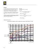
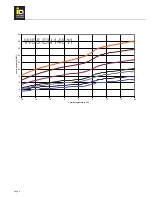
Page 6: ...ny 4 persons Service water consumption requirement 4 x 0 25 kW 1 kW Heating output required 16 kW Standard outside temperature for Germany 16 C Off period factor 1 1 Heating output required service water consumption required heating output required x off period factor 18 7 kW 0 5 10 15 20 25 30 35 40 45 20 15 10 5 0 5 10 15 20 W35 EN14511 CL 33 CL 27 CL 22 CL 15 CL 12 CL 10 CL 8 outside temperatur...

Page 7: ... 10 5 0 5 10 15 20 W35 EN14511 CL 33 CL 27 CL 22 CL 15 CL 12 CL 10 CL 8 outside temperature C heating capacity kW 0 5 10 15 20 25 30 35 40 45 20 15 10 5 0 5 10 15 20 W45 EN14511 CL 33 CL 27 CL 22 CL 15 CL 12 CL 10 CL 8 outside temperature C heating capacity kW ...

Page 8: ...Page 8 0 5 10 15 20 25 30 35 40 45 20 15 10 5 0 5 10 15 20 W55 EN14511 CL 33 CL 27 CL 22 CL 15 CL 12 CL 10 CL 8 outside temperature C heating capacity kW ...

Page 9: ...t a d e f g i j k l m 8 1100 1535 750 640 865 690 1035 575 460 350 240 125 125 10 1100 1535 750 640 865 690 1035 575 460 350 240 125 125 12 1200 1635 780 640 965 720 1135 575 460 350 240 125 125 15 1200 1635 780 640 965 720 1135 575 460 350 240 125 125 22 1200 1735 880 740 965 820 1135 675 540 400 260 125 125 27 1300 1935 980 740 1165 920 1235 675 540 400 260 125 125 33 1300 1935 980 740 1165 920 ...

Page 10: ...relevant machines in question Efficient and fault free operation can only be ensured if the appropriately sized connection elements are used Even light shafts which are too small enlarge the pressure loss of the air routeing These must therefore be of a sufficient size Light shafts must have a rainwater run off Air inlet air outlet The options for how the air inlet and air outlet are desig ned are...

Page 11: ... advance These openings must be insulated with closed pore insulating material minimum thickness 50mm Space required accessibility To guarantee maintenance and operation of the heat pump the following minimum distances must be obser ved Front side operation and maintenance side 800mm Maintenance side 500mm Observing these distances will help ensure problem free system maintenance and operation min...

Page 12: ...t pump for this purpose Customer preparation Specified dimensions include clearances A noise insulating door should be fitted Minimum thickness of the wall insulation is 50mm a b d c e e f g a b d c e e f g Type a b c d e f g 8 1000 830 650 830 90 650 650 10 1000 830 650 830 90 650 650 12 1100 930 680 930 90 650 650 15 1100 930 680 930 90 650 650 22 1100 930 780 930 90 650 650 27 1200 1130 880 113...

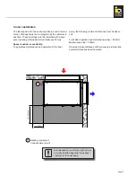
Page 13: ...ght connection Pos Optional accessories Prod no Prod no Prod no Prod no Prod no Prod no Prod no 342 Weather protected inlet grille Steel galvanised 343 Wire inlet grille Steel galvanised 345 Weather protected outlet grille 192 365 Steel galvanised 346 Wire outlet grille 192 366 Steel galvanised 192 376 192 346 192 356 192 375 192 342 192 352 192 372 TERRA CL 08 33 Corner installation 192 341 192 3...

Page 14: ... the wall opening prepared by the customer has been insulated The machine can then be moved into the corner The heat pump may only be moved with the panels fitted If there are any air gaps on the outlet or inlet openings due to the ground being uneven this can be corrected using the adjustable machine feet Noise Noise level in the installation room depends on various factors such as room size abso...

Page 15: ...s a short circuit may occur between the sup ply and exhaust sides with this method the inlet and out let should be positioned as far apart as possible The unit can be separated from any shrubbery by fitting dividing walls if necessary Option 2 This method is equivalent to corner installation This method can be used if corner installation is not possible due to space restrictions or if a gap needs ...

Page 16: ...Page 16 Pos 341 Pos 342 343 Pos 421 Pos 423 424 Pos 425 Pos 426 Pos 427 428 Option 1 Pos 341 Pos 342 343 Pos 421 Pos 423 424 Pos 426 Pos 427 428 Option 2 ...

Page 17: ...90 insulated 426 Wall connection insulated Pos Optional accessories Prod no Prod no Prod no Prod no Prod no Prod no Prod no 342 Weather protected inlet grille Steel galvanised 343 Wire inlet grille Steel galvanised 427 Weather protected outlet grille Steel galvanised 428 Wire outlet grille Steel galvanised 388 Side panels 192 408 for free cut out 84 192 351 37 192 371 192 353 225 192 372 550 192 3...

Page 18: ... Minimum thickness of the wall insulation is 50mm a b c d e f g Type a b c d e f g 8 1000 830 500 700 650 720 1100 10 1000 830 500 700 650 720 1100 12 1100 930 500 700 650 770 1100 15 1100 930 500 700 650 770 1100 TERRA CL 08 15 All dimensions in mm Standard duct Version 1 90 for 1000mm duct length length can be cut to size as required ...

Page 19: ...ickness of the wall insulation is 50mm a b c d e f g h Type a b c d e f g h 8 1000 830 500 700 650 720 1100 270 10 1000 830 500 700 650 720 1100 270 12 1100 930 500 700 650 770 1100 270 15 1100 930 500 700 650 770 1100 270 TERRA CL 08 15 All dimensions in mm Standard duct Version 2 180 for 1000mm duct length length can be cut to size as required ...

Page 20: ...sing the adjustable machine feet Significant pressure against the wall should be avoided Outlet panels The outlet panel is mounted using the four clamps sup plied Duct Assemble the duct using the screw set supplied The fitting length should then be checked If the straight duct is too long two rivets can be bored open on one side so that the flange can be removed The duct can then be cut to length ...

Page 21: ...Page 21 Installation Flexible air hose This option is suitable for connecting to air openings at varied hights The air hose is supplied in three different lengths and can be cut to length as required ...

Page 22: ...ces Wall opening should be thicker around the wall insulation Minimum thickness of the wall insulation is 50mm Type a b c d e f 8 1000 830 620 620 650 1000 10 1000 830 620 620 650 1000 12 1100 930 720 720 650 1000 15 1100 930 720 720 650 1000 All dimensions in mm Flexible hose page TERRA CL 08 15 ...

Page 23: ...383 Wall flange insulated 387 Hose clip Pos Optional accessories Prod no Prod no Prod no Prod no 342 Weather protected inlet grille Steel galvanised 343 Wire inlet grille Steel galvanised 384 Weather protected outlet grille Steel galvanised 385 Wire outlet grille Steel galvanised 382 Outlet panel on top foamed 388 Panels right left required when outlet is on top 192 382 192 392 192 388 192 398 192...

Page 24: ...he panels fitted If there are any air gaps on the outlet or inlet openings due to the ground being uneven this can be corrected using the adjustable machine feet Significant pressure against the wall should be avoided Outlet panels The outlet panel is mounted using the four clamps sup plied Wall flange The wall flange must be fitted to the air outlet opening using suitable mounting materials There...

Page 25: ... 1 3 2 4 The following steps need to be carried out to convert the hydraulics Remove the right hand side pipework and unfasten the cable fittings Unfasten the connection angle with the crown nuts on the plate heat exchanger Turn the lower elbow joint by 180 and screw back on Screw on the fixing clips and threaded rods Install the circulation pump and turn the pump head back Then screw on the pipe ...

Page 26: ...mmonia sulphur chlorine etc Condensation pipe The condensation pipe must be laid so that the water can also flow off even at outside temperatures below 0 C A siphon should be fitted Heating connections In general all lines outdoors should be kept as short as possible All pipes and wall openings must be professio nally heat insulated and frost protected during installati on A self regulating compan...

Page 27: ...oated 302 Weather protected inlet grille Anodised aluminium 303 Weather protected outlet grille 192 323 Anodised aluminium Crankcase heater Pos Optional accessories Prod no Prod no Prod no Prod no Prod no Prod no Prod no 305 Lockable door 306 Insulated cover 192 306 192 326 TERRA CL 08 33 Set for external installation 192 330 192 300 192 310 192 301 192 311 192 302 192 331 192 312 192 332 192 303 ...

Page 28: ...s steel radiators or storage tanks due to oxygen diffusion Corrosion products can be deposited in the condenser and may cause heating losses to the heat pump or high pressure faults For this reason open heating systems or steel pipe installations in combination with plastic pipe underfloor heating which is not diffusion tight should be avoided Heating water quality Depending on the quality of the ...

Page 29: ...ource heat pump with Hygienik and layer separate plate The electric heating immerser is activated when the system fails to reach an adjustable outside temperature bivalence point there is a high pressure or low pressure fault or there is a thermal relay fault ...

Page 30: ...mption or very low hot water consumption it is advisable to separate the buffer tank and the Hygienik The tank in question is heated via the priority valve as required For hot water supply a storage tank without layer separate plate is used An electric heating immerser and a heating circulation pump are installed in model sizes to TERRA CL15 Available as an accessory for larger heat pumps ...

Page 31: ... output 2 terminal X3 66 needs to be programmed for this function In addition the collector tank sensor termi nal X4 90 and the collector flow sensor terminal X4 91 should be connected Depending on the size a solar panel of max 12m can be connected to the solar coil in the Hygienik tank For larger collector surfaces an external pipework module with plate heat exchanger and appropriate solar contro...

Page 32: ...ienik layer separate plate and heating buffer Connecting the oil boiler to the electric heating im merser output Dependent on output when an adjustable outside tem perature value is not reached and in the event of a high pressure low pressure fault or thermal relay fault ...

Page 33: ... account the building characteristics and turn on optimisation Hot water loading circuit with different operating modes e g hot water priority or parallel operation Economy temperature Adjustable legionella protection function Adjustable storage pump run on Storage tank discharge protection Limitation and safety functions Optimum adjustment of the control characteristics for different heat generat...

Page 34: ...s from the power supply company transmission stations and other commu nications devices generates an invisible electrosmog This interference affects all systems both biological us as living beings as well as technical electrical systems They generate undesirable fault currents which can have different effects The effects on biological systems can only be guessed at currently but the effects on tec...

Page 35: ... into the heat pump on the right and left The loading pump and an electric heating immerser are included as standard with the TERRA CL 08 15 only In TERRA CL 22 33 heat pump the IDM loading pump ran ge or a suitable loading pump should be used An additio nal electric heating immerser can be installed on the heat pump inlet in a pipe casing ...

Page 36: ...20 L1 21 L2 22 L3 23 N 24 PE X1 1 L X1 3 PE 2 N 4 L 6 N 7 PE 8 L 9 N 10 PE 14 L1 15 L1 5 L 11 L 12 N 13 PE 16 L1 17 N 18 PE X3 55 56 57 58 59 60 61 62 63 6 X4 81 82 83 84 85 86 87 88 89 9 boiler loading pump priority valve pump for heating circle without mixer buffer loading pump mixer HC1 open brown mixer HC1 close black pump HC1 mixer HC2 open brown control 2 heating generator phase 230V 50Hz 1x...

Page 37: ...VE1 varible input 1 KVLF solar kollector sensor VF2 flow sensor HV2 VE2 varible input 2 VE3 varible input 3 KSPF solar buffer sensor relais for speed control led pumps boiler loading pump priority valve pump for heating circle without mixer buffer loading pump mixer HC1 open brown mixer HC1 close black pump HC1 mixer HC2 open brown mixer HC2 close black pump HC2 control 2 heating generator variabl...

Page 38: ... 21 L2 22 L3 23 N 24 PE X1 1 L X1 3 PE 2 N 4 L 6 N 7 PE 8 L 9 N 10 PE 14 L1 15 L1 5 L 11 L 12 N 13 PE 16 L1 17 N 18 PE X5 1 2 3 4 5 6 7 8 1 X2 2 3 4 5 6 PE E1 PE N L L N L N 55 56 N L X3 55 56 57 58 59 60 61 62 63 64 65 66 X4 81 82 83 84 85 86 87 88 89 90 91 close op room station remote control RSS T RFF T AF external sensor RLF PF WF return buffer or heating generator SF service water sensor buff...

Page 39: ...ault output fan EW WVU Idle periode block close o room station rem control RSS T RF AF external sens RLF PF WF return buffer or heating genera SF service water buffer sensor VF1 flow sensor VE1 varible input KVLF solar kollec sensor VF2 flow sensor VE2 varible input VE3 varible input KSPF solar buffer 1 L1 X1 2 L2 3 L3 5 PE 4 N 6 L1 7 L2 8 L3 9 PE 10 L1 11 L2 12 L3 13 N 14 PE 15 L1 16 L2 17 L3 18 ...

Page 40: ...t via a two wire data bus line As this connection is always made in parallel on the same cable the data transfer must be selected via the relevant assigned bus addresses The bus addresses are assigned in accordance with the table below Control unit offset roomstat function bus address heating circuit bus address Basic equipment 10 direct heating circuit mixer heating circuit 1 mixer heating circui...

Page 41: ...Installing RFF room sensor With a room sensor the room temperature can be monito red the required room temperature can be adjusted and the operating mode for a heating circuit can be changed remotely The bus address on the offset roomstat is used to set which heating circuit the room sensor and the operating mode adjustment are set for The connection is made via a 4 pole data bus Recommended shiel...

Page 42: ...erser and the heat pump compressor Activation This switch is used to activate the automatic control of the heat pump Electric heating immerser The following operating modes are possible 0 the electric heating immerser is off I the electric heating immerser is activated automati cally when the bivalence points is not reached and the control issues an output dependent request or if a fault occurs in...

Page 43: ...eat supplied Check whether the inlet opening or the evaporator pa ckage is contaminated or the air inlet or outlet is unobs tructed Air source heat exchanger evaporator is heavily iced over please contact your service technician Fan speed is too low please contact your service technician Fault free functioning is not possible as the outside temperature is too low 15 C A loss of refrigerant means t...

Page 44: ...ER FAMILY is available to you at all times on our website www idm energie com We look forward to receiving your registration IDM service technology IDM Academy Your on site IDM partner The power family IDM HEADQUARTERS IN MATREI IN EASTERN TYROL AUSTRIA IDM ENERGIESYSTEME GMBH Seblas 16 18 9971 Matrei in Osttirol Austria Phone 43 0 4875 6172 0 Fax 43 0 4875 6172 85 Email team idm energie at Semina...

Reviews: