2
15
INSTALLATION INSTRUCTIONS
Read the safety instruction first.
To change the modulator settings, open the plastic cover.
If RF IN connector on the modulator is not used, connect the 75
Ω
load supplied.
When modulators are cascading, space between channels must be no less than two (for example 21, 24, 27 and etc.).
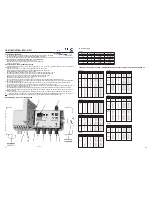
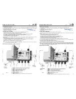
To wall mount the modulator - screw the modulator to the wall (see figure 1).
Do not connect TV antennas to modulator RF IN connector directly. If you intend to combine TV signals of antennas and
the modulator, plug in booster with output-to-input isolation
≥
20 dB between antenna output and RF IN connector.
DEFAULT SETTINGS
1. Output channel E02;
2. Audio subcarrier deviation ±50 kHz (when audio signal level 1 kHz is 775 mV);
3. B/G standard; audio subcarrier 5.5 MHz (Preset
b5
);
4. Test pattern generator OFF (Preset
no
);
5. Frequency shift none (Preset
0
);
6. P/S ratio -16 dB (Preset
I6
);
7. Output signal on (Preset
on
);
8. Sound subcarriers deviation regulator (Preset
0
,
for MT57);
9. Sound mode STEREO (Preset
A5
,
for MT57).
OPERATING
CHANGING OF SETTINGS
The modulator has two modes of operating:
1. normal: sets after plug in;
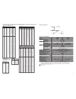
Output channel can be selected in normal mode by pressing buttons “-“ or “+” (see tables 2-11).
2. setting: to enter the setting mode press and hold “-“ and “+” buttons simultaneously for 1 second, to exit setting mode
press and hold “-“ and “+” buttons simultaneously for 1 second.
Select of necessary to change parameter by pressing button “-“ and set necessary mode by pressing “+” button.
1. TV system setting:
a) after switching settings mode, indicator displays current TV system (see table 1);
b) set necessary TV system by pressing “-“ button (see tables 2-11);
c) after TV system changing, modulator sets to first channel of selected TV system (see tables 2-11), other settings
remains unchanged.
2. test pattern generator:
a) press “-“ button;
b) switching between OFF and ON by pressing button “+”,
“no”
- test pattern generator OFF,
“t5”
- test pattern generator ON.
3. fine tuning of video carrier frequency:
a) press button “-“;
b) shift video carrier frequency by pressing button “+” (see table 12).
4. picture/sound ratio switching:
a) press button “-“;
b) switching between 12 dB and 16 dB by pressing button “+”.
5. output signal switching:
a) press button “-“;
b) switching between RF ON and RF OFF by pressing button “+”,
“on”
- RF ON,
“oF”
- RF OFF.
6. sound subcarriers deviation regulation (for MT57):
a) press button “-“;
b) set necessary deviation by pressing button “+“ (see table 13).
7. STEREO/MONO mode switching (for MT57):
a) press button “-“;
b) switch between MONO/STEREO mode by pressing button “+“ (
"A-"
- mono,
"A5"
- stereo).
PROTECTION FROM UNAUTHORIZED ACCESS
To prevent unauthorized access press buttons "-" and "+" simultaneously twice in 0.5 sec. "
LO
" will briefly be displayed.
To revert to normal operation, repeat above procedure. "
UL
" will briefly be displayed. The symbol "
LO
" appears, if you try to
change settings in locked mode.
SOUND SUBCARRIER DEVIATION SETTING
MT47
: When input signal level is from 340 mV to 775 mV in both audio inputs, use a regulator (figure 1, position 11) to set
the sound subcarrier deviation ±50 kHz. The factory set sound subcarrier deviation is ±50 kHz for an input signal level of
775 mV in both audio inputs.
MT57
: The factory set sound subcarier deviation is ±50 kHz for an input signal 1 kHz/775 mV in both audio inputs
(Preset
0
). Use software control for audio deviation regulation ±6 dB (see table 13).
OUTPUT SIGNAL LEVEL ADJUSTMENT
Use a regulator (figure 1, position 6) to adjust an output level. Output level adjustment range is 0
÷
-20 dB.


