


2
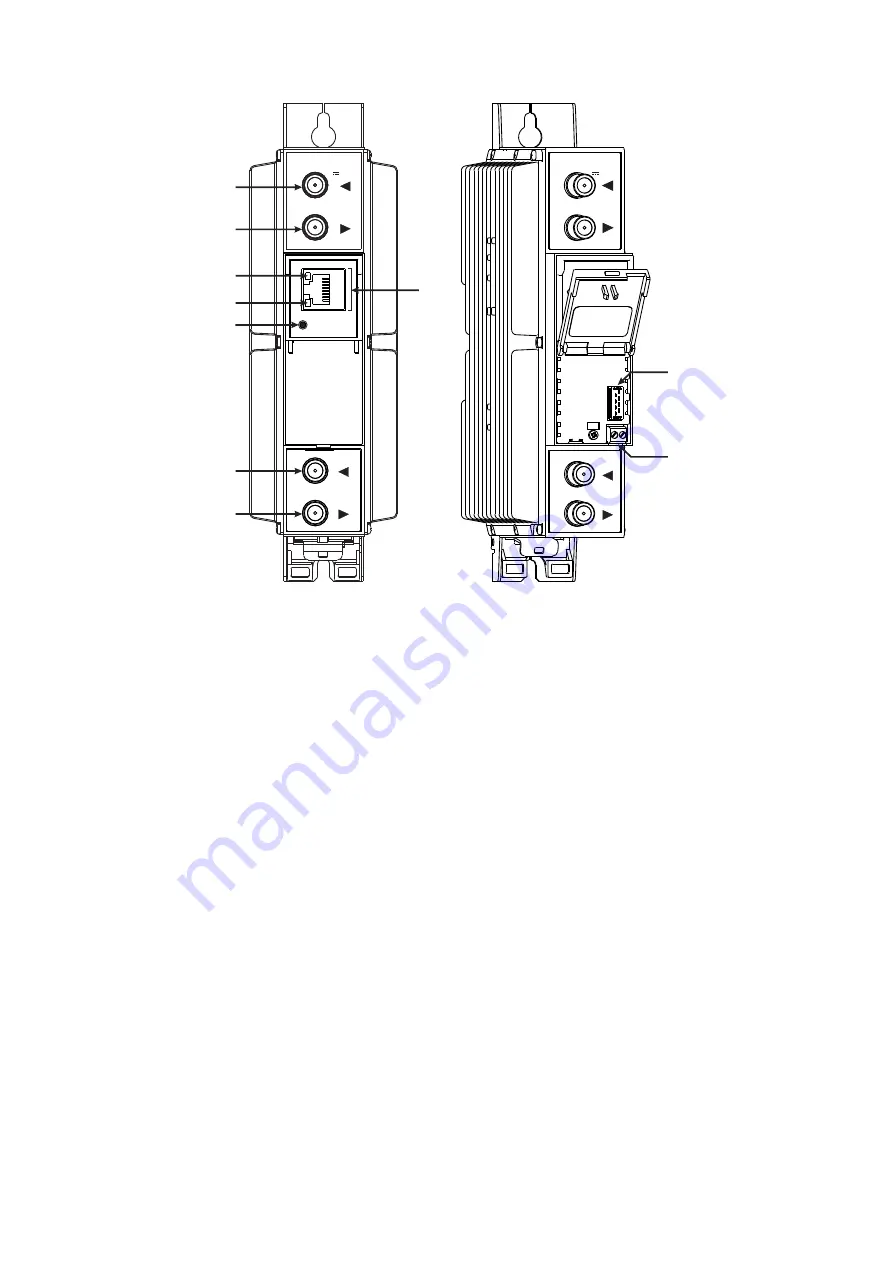
3. External view
1
- ◄ - RF input of SAT IF signal, DC output for LNB.
2
- ►- RF output (input signal loop-through). F socket.
3
-
ETHERNET
- control Ethernet interface. RJ45 socket.
4
- ACTIVITY (yellow) indicator of the control Ethernet interface.
5
- LINK (green) indicator of the control Ethernet interface.
6
-
RESET
- reset and default IP button.
Press this button shortly to restart the module. Press this button for
more than three seconds to set default IP address of the control
Ethernet interface.
7
- RF input (output signal loop-through). F socket.
8
- RF output. F socket.
9
- Power distribution bus connector.
10
- +12 V DC powering input. Screw terminal.
Figure 1. External view of the transmodulator
DC OUT 13/18V
1A max
DC IN 12V
--
+
+
tdx4168
RESET
ETHERNET
TERRA
1
2
4
5
3
6
7
8
tdx4168
DC IN 12V
--
+
+
9
10
DC OUT 13/18V
1A max
DC OUT 13/18V
1A max


