6
Device information table
This shows the following data of module:
“Device model”: model of the module.
“Serial number”: serial number of the module.
“Software version”: module software version number.
“System time”: current time, synchronized from the TDT table of the input stream or NTP server. Local time offset can be
selected in the "IP settings" tab, see section
6.9 "IP settings"
.
“Up time”: time passed from last power-up or restart of the module.
Output bitrates table
It displays the output bitrate status of each channel in real time, Horizontal bar shows the percentage of used available
bandwidth in the channel. The 1
st
number right to the bar shows actual bitrate in Mbps. Next number shows maximum allowed
bitrate in the channel and it depends on modulation parameters. Ensure that actual bitrate would not reach more than 95%
of available bandwidth. Otherwise bitrate overflow may occur.
System status table
It represents the following parameters at real time: Processor load in percents, internal temperature in degrees of Celsius,
power voltage in Volts.
Other device in the network
If there are any modules in the network their status and diagnostic information will be displayed as it is in Figure 7 "General
information screen". If modules status is red press the down arrow and diagnostic errors will be displayed. Make sure, that
Ethernet router is configured properly to pass SSDP packets (239.255.255.250:1900 and 239.255.255.246:7900). Also make
sure that all modules are connected to the same Ethernet network
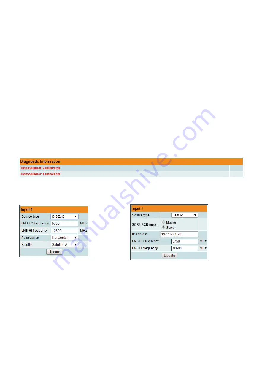
Diagnostic information table
It displays all module errors and comments how to eliminate them.
Figure 8. Diagnostic information table with errors
6.3 RF inputs
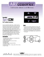
Figure 9. "Input 1" table (DVB-S/S2 input only)
Figure 10. "Input 1" table "Source types = dSCR"
The Figure 9 "Input 1" table in modules with DVB-S/S2 input consists of the following parameters:
"LNB LO frequency" - the LNB local oscillator lower frequency in megahertz. Use 9750 MHz for the universal converter.
"LNB HI frequency" - the LNB local oscillator upper frequency in megahertz. Use 10600 MHz for the universal converter.
“LNB Power” - power supply of the converter – can be set to “0”, “13V”, “18V”, “13V/22kHz”, “18V/22kHz”.
"Polarization" - the polarization of converter. Can be "Horizontal" or "Vertical".
“Source type” - the LNB types, there are several: Universal, Quadro, DiSEqC, dSCR EN50607, SCR EN50494 - see Figures
9, 10.


