


7
“Universal LNB” - power supply voltage of the converter is chosen according
to the selected polarization – 18 V Horizontal, 13 V Vertical; the 22 kHz is
set depending on given "LNB HI frequency" "LNB LO frequency" and “Input
frequency” parameters.
For example
:
LNB Hi=10,600, LNB Lo=9750, then F=(950+10,600+2150+9750)/2=11,725 MHz.
“DiSEqC” - then DISEQC commands are used to select the satellite. Possible
commands: “Satellite A”, “Satellite B”, “Satellite C”, “Satellite D”, Vertical or
Horizontal polarization.
"dSCR" – first select source type as shown in Figure 10, then select
“dSCR/SCR mode“ Master or Slave (Master for module which has direct
connection to Unicable multiswitch or LNB and Slave for modules connected by
loop through). If Slave was selected, additionally type the IP address of Master
module. All the modules in the dSCR/SCR group must be in the same Ethernet
network. Next select "SAT input" and "User band", type in frequencies, symbol
rate press “Update” button and observe "dSCR" status.
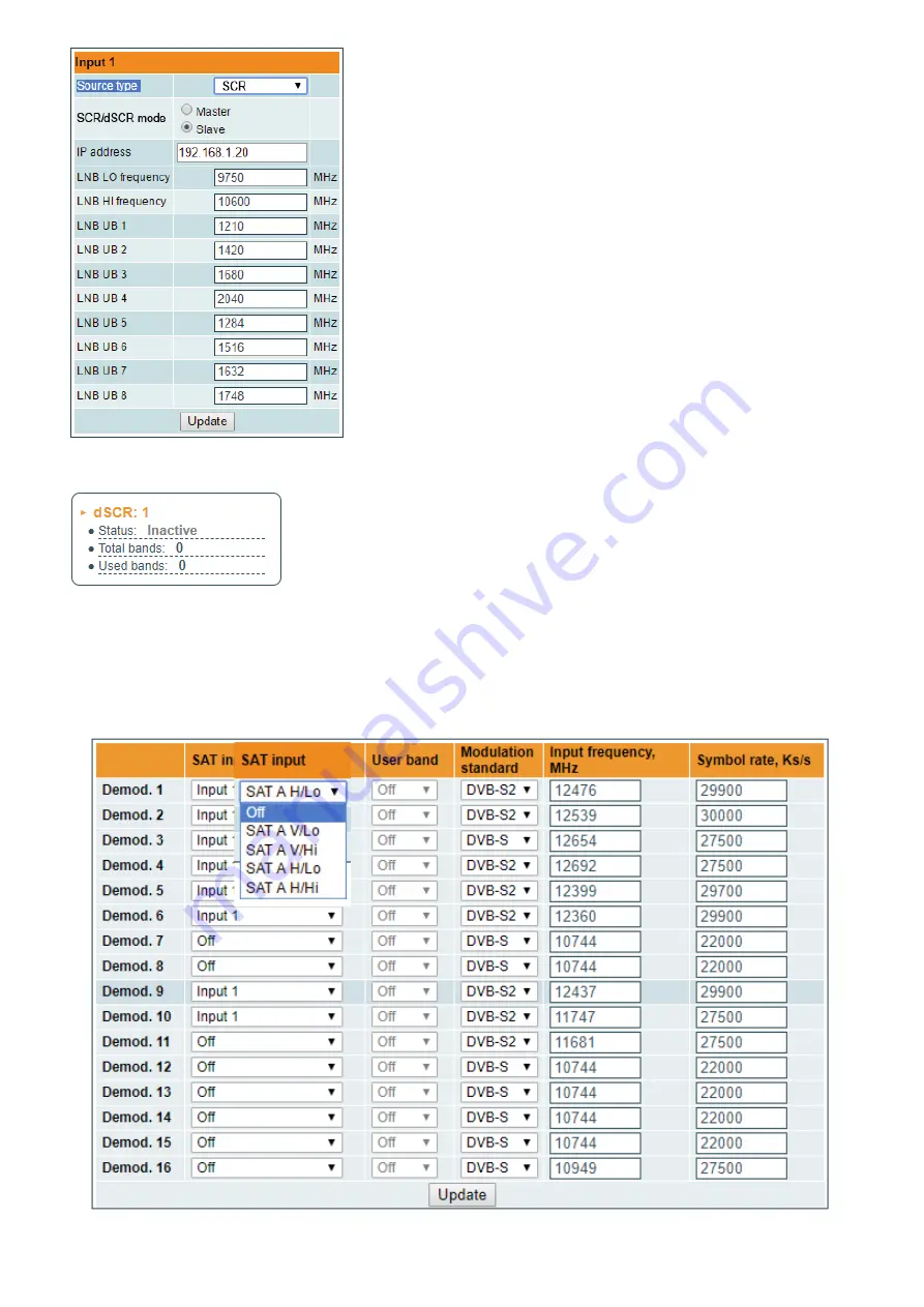
"SCR" - same as "dSCR", just the user band frequencies must be typed in
manually as shown in Figure 11.
Figure 11. "Input 1" table "Source types = SCR"
Figure 12. Status table
The Figure 13 "Demodulator settings table" in modules with DVB-S/S2 input consists of the following parameters:
„SAT input“ - A parameter that can switch demodulator off or connect to any available RF input.
“User band” - parameter used in dSCR/SCR Switches.
„Input frequency“ - parameter is a frequency of transponder in MHz.
„Symbol rate“ - parameter is a symbol rate of transponder in kSym/s.
Figure 13. Demodulator
settings table


