8
Revision H
August 19, 1996
2.3.3
NOISE AND INTERFERENCE (CONTINUED)
Noise and/or interference is usually heard in the audio systems, although it may also
be detected as an interference to indicator operation. Unless a strong suspicion of the
exact source is suspected, it is best to begin a process of elimination, in the following
order:
1.
Power Source: Check for low voltage when the avionics load is
applied. A high resistance battery cell in the A/C can cause
numerous problems. View the avionics power line at the avionics
master and at the affected unit for noise on the power line. If
present, try to categorize the frequency (eg. alternator whine, which
may be caused by one or more bad alternator diodes, or if
interference is present only when a communication unit is
transmitting, etc.). If the noise is present or worse at the affected
unit than at the avionics master, investigate the harness for noise
coupling between wires. If necessary, disconnect the affected unit
power from the aircraft power source and connect to an external
power supply or battery.
2.
Power Ground: View the power ground line at the avionics master
and the affected unit. If noise is discerned at the master source,
ground strapping may be corroded or partially broken. If only at unit,
a larger wire size or wire re-routing may be required.
3.
Interference: Both noise and interference may be either conducted
or radiated, and in some cases electromagnetically coupled between
units. If it is determined that the noise or interference is eliminated
whenever another avionics unit is not transmitting, first investigate the
radiated alternative. Insure complete and proper bonding of antennas
to the aircraft surface, and check the coaxial cable and all shield
connections and connectors. Review the manufacturer’s
recommendations for antenna separations. Be aware that antenna
radiation directly to conductors at the rear of mounting trays or units
may occur if shields are stripped too far back from the connector or
are improperly grounded. Disconnecting the interfering antenna and
substituting an external dummy load may assist diagnosis. Conducted
interference usually occurs through paths which are shared by the
avionics equipment such as power lines, ground points, audio
equipment, or induced interference between adjacent wires or
harnesses. Review the manufacturer’s recommendations for
shielded wiring and ground points, and for separation of specific
wires. Measure ground points for a small but perceptible resistance
to true ground and view power lines with an oscilloscope, turning
each unit on and off to detect changes. Recheck common or
adjacent connections to jacks, plugs, or shared equipment such as
power converters, breakers, or audio panels.
4.
Compromise: In some cases noise or interference may be subdued
but not eliminated. With the inefficient and imperfect platform
provided by the aircraft for antennas and power source, etc, complete
Summary of Contents for TN 200D
Page 16: ...12 Revision H August 19 1996 THIS PAGE INTENTIONALLY LEFT BLANK ...
Page 18: ...14 Revision H August 19 1996 THIS PAGE INTENTIONALLY LEFT BLANK ...
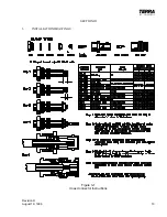
Page 19: ...Revision H August 19 1996 15 Figure 3 2 Coax Connector Instructions ...
Page 20: ...16 Revision H August 19 1996 THIS PAGE INTENTIONALLY LEFT BLANK ...
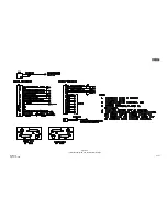
Page 21: ...Revision H August 19 1996 17 18 Figure 3 3 TN 200D Outline Dimensions ...
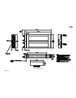
Page 22: ...Revision H August 19 1996 19 20 Figure 3 4 Typical Outline Drawing Dual Tray ...
Page 23: ...Revision H August 19 1996 21 22 Figure 3 5 Outline Drawing 3 Option ...
Page 24: ...Revision H August 19 1996 23 24 Figure 3 6 Interconnect Drawing TN 200D Without Glideslope ...
Page 25: ...Revision H August 19 1996 25 26 Figure 3 7 Interconnect Diagram TN 200D With Glideslope ...
Page 33: ...34 Revision H August 19 1996 THIS PAGE INTENTIONALLY LEFT BLANK ...
Page 35: ...36 Revision H August 19 1996 THIS PAGE INTENTIONALLY LEFT BLANK ...
Page 37: ...38 Revision H August 19 1996 6 2 INSTALLATION NOTES ...


