Revision H
August 19, 1996
9
2.3.3
WIRING AND HARNESSING (CONTINUED)
elimination of the problem may be very expensive or impossible (eg.
if there is simply not enough space to provide ground plane or
antenna separation as recommended). Or, the aircraft strobe noise is
audible but not objectionable, etc. These problems should be
discussed early and thoroughly with the customer.
2.3.5
SUMMARY
The paragraphs above are not intended to be highly technical, completely thorough, or
extensive, but serve as a reminder for certain precautionary or follow-up procedures
for general avionics installations. Trimble is prepared to assist at any point with
additional information, hints, or literature. Simply call 1-800-487-4662 and ask for
technical assistance.
2.4
INSTALLATION
Installation of any equipment in an aircraft requires that the work be performed by a
Certificated Radio Repair Station with appropriate ratings. The installing agency must
complete an FAA Form 337 and compute a new weight and balance for the aircraft for
insertion in the Aircraft Flight Manual. Unless the mechanic is the designated inspector for a
Certificated Radio Repair Station or holds an Inspection Authorization, the work is subject to
inspection and approval of an FAA inspector or the holder of an Inspection Authorization.
The following items and suggestions should be considered prior to installation of your Terra by
Trimble TN 200D Navigational Receiver.
1.
Discuss the location of this receiver with your customer, preferably in a position that
provides ease of operation.
2.
Avoid installing the TN 200D near heat sources. If unavoidable, insure additional
cooling is provided.
3.
Insure that adequate clearance exists behind the panel for sleeve, connectors, and
additional cooling if required. A minimum of 14.00" (35.56 cm) is recommended.
4.
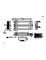
Refer to Terra by Trimble TN 200D Outline Drawings for panel cut-out details and
mounting dimensions as well as pertinent notes.
5.
Install the sleeve assembly in the instrument panel. Insure compliance with standards
set forth in the FAA Aircraft Inspection and Repair Document AC 43.13-2A.
Note:
Insure that the sleeve is installed with the large opening toward the top.
6.
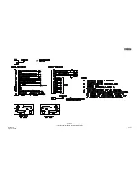
The 15 pin “D” connector assembly supplied with the Terra by Trimble TN 200D
must be wired correctly to the aircraft avionics systems or severe damage may result
to the Terra by Trimble TN 200D or other systems. The interconnecting wiring for
the 15 pin “D” connector is shown in Figure 3-6 (without glideslope) and Figure 3-7
(with glideslope). Comply with standards set forth in FAA Aircraft Inspection and
Repair Document AC 43.13-1A Section 7 and other pertinent FAR’s as required.
Insure MIL-SPEC wire is utilized for all interconnects.
Summary of Contents for TN 200D
Page 16: ...12 Revision H August 19 1996 THIS PAGE INTENTIONALLY LEFT BLANK ...
Page 18: ...14 Revision H August 19 1996 THIS PAGE INTENTIONALLY LEFT BLANK ...
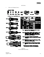
Page 19: ...Revision H August 19 1996 15 Figure 3 2 Coax Connector Instructions ...
Page 20: ...16 Revision H August 19 1996 THIS PAGE INTENTIONALLY LEFT BLANK ...
Page 21: ...Revision H August 19 1996 17 18 Figure 3 3 TN 200D Outline Dimensions ...
Page 22: ...Revision H August 19 1996 19 20 Figure 3 4 Typical Outline Drawing Dual Tray ...
Page 23: ...Revision H August 19 1996 21 22 Figure 3 5 Outline Drawing 3 Option ...
Page 24: ...Revision H August 19 1996 23 24 Figure 3 6 Interconnect Drawing TN 200D Without Glideslope ...
Page 25: ...Revision H August 19 1996 25 26 Figure 3 7 Interconnect Diagram TN 200D With Glideslope ...
Page 33: ...34 Revision H August 19 1996 THIS PAGE INTENTIONALLY LEFT BLANK ...
Page 35: ...36 Revision H August 19 1996 THIS PAGE INTENTIONALLY LEFT BLANK ...
Page 37: ...38 Revision H August 19 1996 6 2 INSTALLATION NOTES ...


