4-2
Revision A
November 25, 1996
4.5
FREQUENCY TRANSFER
As previously described in Section 4.3, simply pressing this button will “swap” frequencies
between active and standby windows.
As will be covered in the next section, depressing this button also cancels the channel
memory display.
The transfer button must be used in order for the last frequencies used to be displayed after a
power interruption. For example, say you are tuned to 118.00 in the active display and
121.60 in the standby display. Pressing the transfer button will insure that the unit will
display “121.60 118.00” after any power interruption. Failure to do this transfer will cause
the unit to come up with 118.00 in the active display and the last transferred frequency in the
standby display.
4.6
COMM TUNING KNOB OPERATING SEQUENCE
A.
Pushing the tuning knob in for approximately one-third of a second will cause the last
two digits of the MHz (Example 1XX.XX) standby display to blink. The leading 1
remains solid since it never changes.
B.
Rotating the knob will now tune the MHz. Scrolling past the end of the frequency
range (up or down) will cause the frequency to “wrap around” to the other end of the
range (e.g., scrolling up past 136, wraps to 118).
C.
Pushing the knob again for approximately one-third of a second will shift the cursor
control from MHz to kHz (Example 1XX.XX) causing the MHz digits to light steady
and the kHz digits to blink.
D.
In the same manner as above, rotating the knob will now tune kHz.
E.
Pushing the knob again for approximately one-third of a second will cause all digits
to display steady.
Notes:
1.
Pushing the <—> button at any time during the tuning sequence will cause the
frequency in the standby display to switch to active and the active to standby
as well as canceling the cursor tuning, if activated.
2.
The software will not let the user select an invalid frequency, below 118.000
or above 136.975.
3.
Tuning with the continuous mode is still available without utilizing the
cursor.
4.7
MEM (MEMORY) OPERATING SEQUENCE
A.
Pressing the MEM button will call up the last used or programmed memory position.
B.
Repeatedly pushing the MEM button will cycle upwards through the memory
positions.
C.
Alternately, holding the MEM button in will cause the unit to cycle through the
memory positions at a rate of one position every one-third of a second.
Summary of Contents for TX 760D
Page 24: ...3 2 Revision A November 25 1996 THIS PAGE INTENTIONALLY LEFT BLANK ...
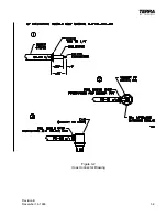
Page 25: ...Revision B December 16 1996 3 3 Figure 3 2 Coax Connector Drawing ...
Page 26: ...3 4 Revision A November 25 1996 THIS PAGE INTENTIONALLY LEFT BLANK ...
Page 27: ...Revision A November 25 1996 3 5 Figure 3 3 Adjustment Locations ...
Page 28: ...3 6 Revision A November 25 1996 THIS PAGE INTENTIONALLY LEFT BLANK ...
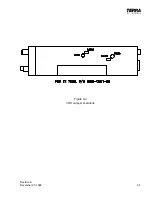
Page 29: ...Revision A November 25 1996 3 7 Figure 3 4 VOX Jumper Locations ...
Page 30: ...3 8 Revision A November 25 1996 THIS PAGE INTENTIONALLY LEFT BLANK ...
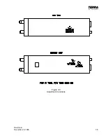
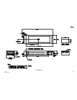
Page 31: ...Revision A November 25 1996 Figure 3 5 Sheet 1 of 2 Outline Dimensions 3 9 10 ...
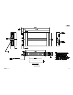
Page 32: ...Revision A November 25 1996 Figure 3 5 Sheet 2 of 2 Outline Dimensions 3 11 12 ...
Page 33: ...Revision A November 25 1996 Figure 3 6 Interconnect Diagram 3 13 14 ...
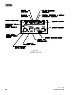
Page 39: ...4 6 Revision A November 25 1996 Figure 4 1 Front Panel Controls ...
Page 41: ...5 2 Revision A November 25 1996 THIS PAGE INTENTIONALLY LEFT BLANK ...
Page 43: ...6 2 Revision A November 25 1996 6 2 INSTALLATION NOTES ...

