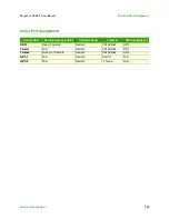
Ethernet Out
127
RangePro RPX8-P User Manual
N • Breakout Board Connections and Pinouts
•
.
Ethernet Out
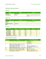
Extension of the Ethernet port from the radio system, typically the J4 WAN Ethernet port of the Picoradio.
While the Picoradio uses a 9-pin connector, it only uses the first five pins for standard Ethernet connectivity.
This connector follows the same pinouts.
•
Connector ID:
J3
•
Breakout board connector:
JST SM05B-GHS-TB(LF)(SN)
•
Mating connector:
JST GHR-05V-S
•
Mating connector crimp pins:
JST SSHL-002T-P0.2
•
.
I2C Out
Extension of the I2C port on the carrier board. This is a one-to-one connection that mimics the port on the car-
rier board.
•
Connector ID:
J2
•
Breakout board connector:
JST SM04B-GHS-TB(LF)(SN)
•
Mating connector:
JST GHR-04V-S
•
Mating connector crimp pins:
JST SSHL-002T-P0.2
Table 3. Serial Out Pinout
Pin
Description
1
VCC/VCC
2
TX/TX
3
RX/RX
4
CTS/CTS
5
RX/RX
6
GND
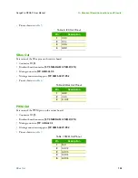
Table 4. Ethernet Out Pinout
Pin
Description
1
2
ETH_2_T-
3
4
N/C
5
ETH_6_R-
Summary of Contents for RangePro RPX8-P
Page 90: ...90 Chapter 12 Contacting TerraView for Support Chapter Contents Support Options 91...
Page 104: ...104 Appendix F LED Meanings Chapter Contents Introduction 105...
Page 119: ...119 Appendix K Configuration Specific Parameters Chapter Contents Load Specific Parameters 120...
Page 121: ...121 Appendix L Making Sense of Motor Tests Chapter Contents Making Sense of Motor Tests 122...
Page 123: ...123 Appendix M Serial Port Assignment Chapter Contents Serial Port Assignment 124...


