Program Battery Memory Charge Settings
135
RangePro RPX8-P User Manual
P • Using the D400 Charger with a RangePro RPX8-P Battery
7.
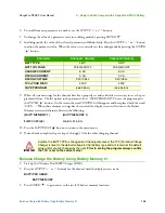
When all system settings for the channel have been properly set and verified, press the
BATT/PROG
“ ”
button to return to the main menu.
8.
If not already completed, repeat steps 2 through 7 for the other charging channel.
Program Battery Memory Charge Settings
Verify the correct Battery Memory settings for BOTH charging channels using the following steps:
1.
Power-on the Ultimate Duo 400W Charger (D400).
2.
Press the
STATUS
“
+
” or “
-
” buttons for the channel until the display screen reads:
[BATT MEMORY 1]
ENTER SET->
3.
Press
ENTER
“
” to gain access to the ten (10) battery memory locations.
4.
Use the
STATUS
“
+
” or “
-
” buttons to scroll through the locations until the screen reads:
BATT/PROGRAM
BATT MEMORY
5.
Press
ENTER
“
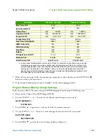
” to verify the correct setting for Battery Memory 1.
Parameter
Channel 1 Value(s)
Channel 2 Value(s)
Max Power Set
200W
200W
Synchronization
a
a. In most cases Synchronization can be set to
ON
but it is important to note that in rare cases Syn-
chronization may prevent one side or another from charging properly if there is a significant mis-
match between battery states. Also note that while Synchronization will ensure the same program
is being used by both sides of the charger, in the case of custom Battery Memory programs it
does not ensure that the programs for each channel are identical. Battery Memory programs must
be independently set on each side of the charger.
OFF
N/A
Safety Timer
ON 150Min
ON 150Min
Capacity Cut-Off
ON 12600mAh
ON 12600mAh
Temp Cut-Off
ON 50C 122F
ON 50C 122F
Temperature Unit
Celsius
Celsius
Rest Time CHG\DCHG
10Min
10Min
NiMH Sensitivity
N/A
N/A
NiCd Sensitivity
N/A
N/A
Key Beep
ON
ON
Buzzer
ON
ON
DC Input Low Cut-Off
11.0 V
11.0 V
Balance Port
Enable
Enable
Load Factory Set
(See Manual)
(See Manual)
Summary of Contents for RangePro RPX8-P
Page 90: ...90 Chapter 12 Contacting TerraView for Support Chapter Contents Support Options 91...
Page 104: ...104 Appendix F LED Meanings Chapter Contents Introduction 105...
Page 119: ...119 Appendix K Configuration Specific Parameters Chapter Contents Load Specific Parameters 120...
Page 121: ...121 Appendix L Making Sense of Motor Tests Chapter Contents Making Sense of Motor Tests 122...
Page 123: ...123 Appendix M Serial Port Assignment Chapter Contents Serial Port Assignment 124...


