Preflight Checklist
98
RangePro RPX8-P User Manual
C • RangePro RPX8-P Manual Flight Checklist
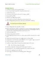
Preflight Checklist
1.
Check batteries to make sure they are properly charged.
2.
Turn on Ground Control Station (GCS)—control unit and client device.
3.
Verify GCS battery status.
4.
Verify volume on the client device and ensure GCS warnings are audible.
5.
Mount payload onto RPX8.
6.
Install battery into flight position on aircraft.
7.
Listen for initial 3 tones from ESCs followed by musical tones from the Cube.
8.
Observe GPS lights flashing blue and red on initial startup to indicate IMU is initializing.
9.
Observe GPS lights flash yellow when IMU is initialized.
10.
Wait for radio connection to complete—could take up to one minute. The GPS status light will turn blue
or green once the radio connection is completed. The connection can be tested by flipping the Strobe con-
trol switch on the GCS and observing a proper response from the aircraft.
11.
Verify data download to GCS.
12.
Verify camera image/connection on GCS.
13.
Verify the Flight mode switch on the GCS is set to Loiter and that the RTL switch on the GCS is switched
down.
14.
Using the software on the GCS client, verify the flight mode is set to Position Hold.
15.
Using the software on the GCS client, verify the HDOP is less than 1.0 (signifies strong sensor operation).
16.
Verify Cube temperature is greater than 43°C or 110°F.
17.
Verify Battery voltage is sufficient for the mission, preferably starting with 24V or more.
Note
Record the battery voltage in the log book.
18.
Verify safety settings found at the bottom of the Summary page are correctly set.
19.
Press hardware safety switch on the GPS for approximately three seconds to activate ESCs.
20.
Listen for tones signifying the unit is ready to fly.
21.
Verify the lights on the GPS have moved from flashing yellow to flashing green.
Do not touch the unit while the IMU is initializing.
IMPORTANT
Summary of Contents for RangePro RPX8-P
Page 90: ...90 Chapter 12 Contacting TerraView for Support Chapter Contents Support Options 91...
Page 104: ...104 Appendix F LED Meanings Chapter Contents Introduction 105...
Page 119: ...119 Appendix K Configuration Specific Parameters Chapter Contents Load Specific Parameters 120...
Page 121: ...121 Appendix L Making Sense of Motor Tests Chapter Contents Making Sense of Motor Tests 122...
Page 123: ...123 Appendix M Serial Port Assignment Chapter Contents Serial Port Assignment 124...

