Introduction
126
RangePro RPX8-P User Manual
N • Breakout Board Connections and Pinouts
Introduction
The RangePro RPX8-P includes a breakout board underneath the airframe, just above the payload area. Con-
nections include 12V power, serial, Ethernet, I2C, SBus, and PWM signals (see
). Depending on your
configuration, some mating cables may be provided as part of the drone kit.
Figure 56. Breakout Board Connectors
Power Out
Power for external devices provided from 12V BEC internal to the chassis. Maximum draw of 5 Amps.
•
Connector ID:
J6
•
Breakout board connector:
Molex 1054301102
•
Mating connector:
Molex 1053071202
•
Mating connector crimp pins:
1053001100
•
.
Serial Out
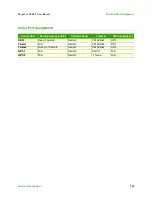
Extension of the Telem2 serial port on the carrier board. In Ardupilot this port is typically referenced as Serial2
and, as long as Serial0 and Serial1 are set to use the Mavlink protocol, the parameter rates are typically set with
the SR2 commands. This is a one-to-one connection that mimics the port on the carrier board.
•
Connector ID:
J4
•
Breakout board connector:
JST SM06B-GHS-TB(LF)(SN)
•
Mating connector:
JST GHR-06V-S
•
Mating connector crimp pins:
JST SSHL-002T-P0.2
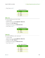
Table 2. Power Out Pinout
Pin
Description
1
Ground
2
12VDC
Summary of Contents for RangePro RPX8-P
Page 90: ...90 Chapter 12 Contacting TerraView for Support Chapter Contents Support Options 91...
Page 104: ...104 Appendix F LED Meanings Chapter Contents Introduction 105...
Page 119: ...119 Appendix K Configuration Specific Parameters Chapter Contents Load Specific Parameters 120...
Page 121: ...121 Appendix L Making Sense of Motor Tests Chapter Contents Making Sense of Motor Tests 122...
Page 123: ...123 Appendix M Serial Port Assignment Chapter Contents Serial Port Assignment 124...

