17
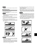
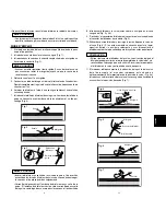
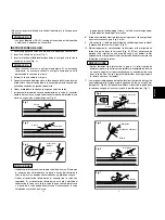
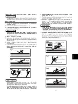
8. Insira o dilatador e a bainha juntos sobre o mini fio-guia e para dentro
do vaso sangüíneo (Fig. 4 e 4a).
9. “Destrave” o cubo do dilatador do cubo da bainha curvando o cubo do
dilatador para baixo (Fig. 5).
10. Remova o dilatador e o mini fio-guia juntos, lentamente, deixando a
bainha no vaso (Fig. 6). Se for necessário efetuar uma injeção ou uma
coleta de amostras neste momento, remova o mini fio-guia somente e
use o cubo do dilatador como uma abertura para injeção antes de
removê-lo.
ATEN
ÇÃ
O
•
Remova o dilatador lentamente da bainha. A remoção rápida do
dilatador pode causar o fechamento incompleto da válvula de uma
via, resultando no fluxo de sangue através da válvula. Se isto ocorrer,
substitua o dilatador dentro da bainha e remova-o outra vez lentamente.
11. O marcador radiopaco fornecerá a localização da ponta da bainha
através de fluoroscopia (o marcador radiopaco localiza-se
aproximadamente a 5 mm proximais da ponta da bainha – Fig. 4a).
Insira o cateter através da bainha e dentro do vaso sangüíneo e
avance-o para a localização desejada (Fig. 7).
PORTUGU
Ê
S
Fig. 6
Mini Guidewire
Dilator
OFF
Fig. 7
Catheter
OFF
Fig. 4
Fig. 4a
Lever
3-Way Stopcock
Mini
Guidewire
Dilator
Sheath
OFF
Approx. 5 mm
Fig. 5
Dilator Hub
Suture Eye
Mini Guidewire
Alavanca
Válvula Reguladora de 3 Vias
Mini Fio-guia
Bainha
Cubo do Dilatador
Buraco da Agulha
Aprox. 5 mm
Mini Fio-guia
Mini Fio-guia
Dilatador
Dilatador
Cateter
4
Fig. 1
Cannula
Fig. 2
Cannula
Mini
Guidewire
Fig. 3
Dilator Hub
Sheath Hub
CAUTION
•
Federal (U.S.A.) law restricts this device to sale by or on the order of
a physician.
INSTRUCTIONS FOR USE
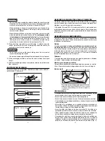
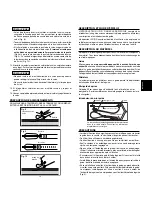
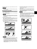
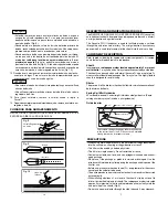
1. Make a small skin incision at the puncture site with a surgical knife.
2. Insert a cannula into the vessel (Fig. 1).
3. Insert the selected flexible end of the mini guidewire through the
cannula into the vessel (Fig. 2).
CAUTION
•
Advance or withdraw the mini guidewire slowly. If resistance is met,
do not advance or withdraw the mini guidewire until the cause of
resistance is determined.
4. Remove the cannula over the mini guidewire.
5. Connect a flushing line to the 3-way stopcock of the introducer sheath.
Fill the sheath assembly completely with heparinized saline, removing
all air.
6. Prime the dilator using a syringe with heparinized saline.
7. Insert the vessel dilator fully into the sheath. The female hub of the
sheath connects with the male hub of the dilator, and locks in place by
means of grip (Fig. 3).
CAUTIONS
•
Insert the dilator into the center of the sheath valve. Forced insertion
of the dilator which misses the center of the sheath valve may cause
damage, and result in blood leakage.
•
Lock the dilator hub into the sheath hub securely. If the dilator hub is
not locked into he sheath hub, only the sheath will advance into the
vessel and the tip of the sheath may damage the vessel. Advancing
the sheath alone may cause damage to the vessel.


