background image

23 


Mounting options 


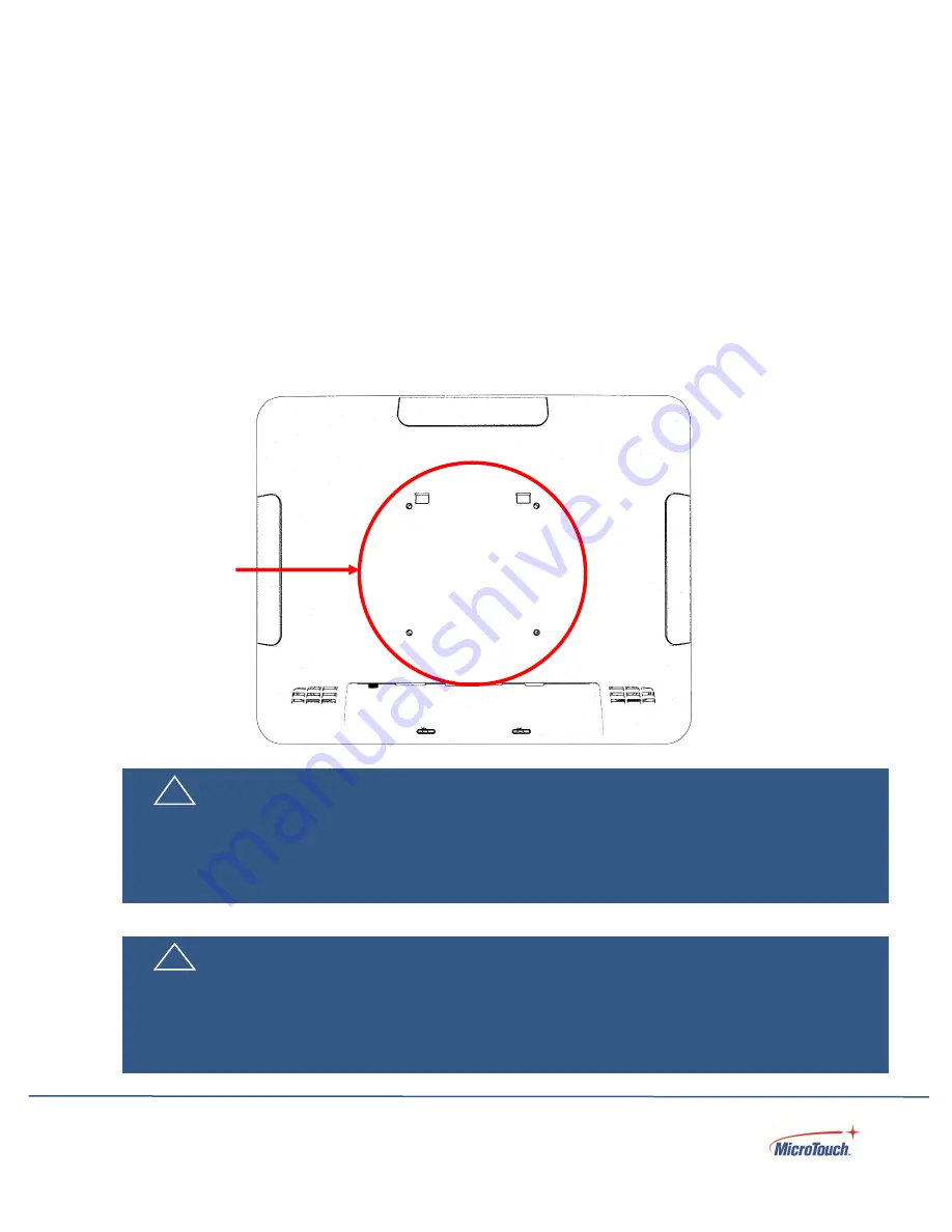
The monitor may be mounted to a stand or other device that has a 100mm x 100mm standard VESA 
mount hole pattern.  


VESA Mount 

The monitor has an integral VESA standard mount pattern that conforms to the “VESA Flat Display 
Mounting  Interface Standard”  which defines  a  physical mounting  interface and  corresponds  to  the 
standards for monitor mounting devices.


VESA Mount


!


Warning 


Please use the correct screws! The distance between the back cover surface and the bottom of the 
screw hole is 8 mm. Please use four M4 diameter screws with 8 mm length to mount the monitor. 


!


Mise en garde 


Veuillez utilizer les vis correcte! La distance entre la surface du capot arrière et le fond du trou de vis 
est de 8 mm. Veuillez utilizer quatre vis de diamètre M4 d’une longueur de 8 mm pour mounter le 
moniteur. 

Summary of Contents for MicroTouch DT-150P-A1

Page 1: ...Rev 2061422 1 DESKTOP TOUCH MONITOR DT 150P A1 USER MANUAL ...

Page 2: ...acking 11 Package Contents 12 Product Setup and Use 13 Configuration and Cable Options 13 Turning the Monitor On and Off 14 On Screen Display OSD 15 Locking the OSD and Power button functions 16 Using the OSD Menus 16 OSD Default Settings 22 Mounting options 23 VESA Mount 23 Specifications and Dimensions 24 Specifications 24 Supported Timings 25 Dimensions without stand 26 Dimensions with stand 27...

Page 3: ...ssory Installation 28 Installing the Stand 28 Routing the cables 29 Installing the optional LCM 30 Installing the optional MSR 30 Cleaning 31 Solutions to Common Problems 32 Warranty Information 33 RoHS Declaration 34 ...

Page 4: ...itted transcribed stored in a retrieval system or translated into any language or computer language in any form or by any means including but not limited to electronic magnetic optical chemical manual or otherwise without prior written permission of MicroTouchTM a TES Company ...

Page 5: ...ler or an experienced radio TV technician for help This device complies with part 15 of the FCC Rules Operation is subject to the following two conditions 1 this device may not cause harmful interference and 2 this device must accept any interference received including interference that may cause undesired operation For IC Canada CAN ICES 3 B NMB 3 B For CE EU The device complies with the EMC Dire...

Page 6: ... appareil respecte la partie 15 des règlements de la FCC Le fonctionnement doit respecter les deux conditions suivantes 1 cet appareil ne doit pas causer de parasites et 2 cet appareil doit accepter tous les parasites reçus notamment ceux pouvant causer un fonctionnement non voulu Pour Industrie Canada Norme canadienne NMB 3 B Pour la CE UE L appareil respecte la directive 2014 30 UE relative à la...

Page 7: ...nance as recommended in this user s manual to maximize the life of your unit Do Disconnect the power plug from AC outlet if the product is not going to be used for an extended period of time Don t Do not operate the product under the following conditions Extremely hot cold or humid environment Areas susceptible to excessive dust and dirt Near any appliance generating a strong magnetic field Warnin...

Page 8: ... éviter Ne jamais utiliser l appareil dans les conditions suivantes des conditions environnementales extrêmes chaud froid ou humidité des endroits remplis de poussières et de saletés à proximité d appareils produisant un fort champ magnétique Mise en garde Pour prévenir les risques d incendie ou d électrocution ne pas exposer le produit à l humidité Mise en garde Prière de ne pas ouvrir ou démonte...

Page 9: ...che est endommagé ou deviant chaud éteignez le moniteur assurez vous que la fiche d alimentation a refroidi et débranchez la fiche d alimentation de la prise Si le moniteur est toujours utilizé dans cet état il peut provoquer un incendie ou un choq électrique Contactez votre revendeur pour le remplacement If any of the following occur remove the power plug from the outlet immediately the monitor i...

Page 10: ...rheating or electrical shock Don t install in a high humidity environment Operating humidity 20 90 Don t insert the power plug into anything other than a grounded 100 240V AC outlet Don t use a damaged power plug or worn outlet The use of extension cords is not recommended The use of the power supply that comes with the MicroTouch product is strongly recommended Don t place the monitor on an unsta...

Page 11: ... Contrast Ratio 800 1 Aspect Ratio 4 3 Brightness 350 cd m2 View Angle H 160 V 140 Video Port 1 VGA DB15 1 HDMI 1 DP 100 mm x 100 mm VESA mount Seamless bezel P cap touch with up to 10 simultaneous touches Plug and Play no touch driver installation required for most modern operating systems Warranty 3 years Unpacking When unpacking please ensure that all the items in the following Accessories sect...

Page 12: ...12 Package Contents No Part Picture Qty 1 LCD Monitor 1 2 AC Power Cord IEC C15 C16 1 8 m 1 3 AC DC adapter 1 4 VGA cable 1 8 m 1 5 USB A to B cable 1 8 m 1 6 Audio Cable 1 8 m 1 7 Stand 1 ...

Page 13: ...ong power cord is used to connect the monitor s AC to DC converter to an AC wall outlet Plug the DC barrel connector into the DC jack on the monitor Plug the AC power cable female connector into the receptacle on the power converter then plug the male connector of the AC cable into a wall outlet Connect the included USB cable from the monitor s touch output to the computer Connect the VGA video ca...

Page 14: ...button of the OSD keypad outlined in red below When the monitor is on pressing the Power button will open a pop up that asks if the monitor is to be turned off If yes press the Power button again Press the Power button one more time in response to the final popup to turn the monitor off Note If there is no video input signal for a preset period the monitor will automatically go into standby mode ...

Page 15: ...n Normal Video Display When OSD Menu is Displayed Activate the main menu Exit selection Exit OSD Brightness Adjust Menu Up Adjust Up Mute Audio Menu Down Adjust Down Select Video Source Select the highlighted item Power on Power off ...

Page 16: ...OSD Active not locked or Inactive locked and Power Active or Inactive 2 Use the UP Down buttons to highlight OSD or Power 3 Press Select 4 Use Up Down buttons to select Yes or No to change the setting 5 Press Select 6 The menu will go away after a few seconds and the selected item will lock if unlocked or unlock if locked or Menu can be pressed to exit and take effect immediately Using the OSD Men...

Page 17: ... because it is analog may require all adjustments so they are all selectable when VGA is being used Contrast Increases or decreases the contrast of the picture Press or select the desired level and then press SELECT Range 0 100 Brightness Increases or decreases the brightness of the picture Press or select the desired level and then press SELECT Range 0 100 H Position Adjust the horizontal positio...

Page 18: ... of the picture Press or to select the desired level and then press SELECT Selectable only when VGA input is in use Range 0 100 Clock Adjust the horizontal dot of the picture Press or to select the desired level and then press SELECT Selectable only when VGA input is in use Range 0 100 Auto Adjust Adjust and fine tune the image to full screen automatically Selectable only when VGA input is in use ...

Page 19: ...K 9300K User Red Adjust the amount of red in color content Range 0 100 Green Adjust the amount of green in color content Range 0 100 Blue Adjust the amount of blue in color content Range 0 100 Sharpness Adjusts the definition of the picture Press or select the desired level and then press SELECT Selectable only when VGA input is in use Range 0 50 ...

Page 20: ...sition Selects the OSD Position center or corners Press to select the rotation Options Top Left Bottom Left Top Right Bottom Right Center OSD H Position Adjusts the horizontal position of the OSD menu Press or to select the desired horizontal position then press SELECT Range 0 100 OSD V Position Adjust the vertical position of the OSD menu Press or to select the desired vertical position then pres...

Page 21: ... OSD language Options English French Deutsch Italian Spanish Japanese Traditional Chinese and Simplified Chinese Source Select Select the Video Input Source Options Auto VGA HDMI DP Display Mode Display the current video source and resolution information Factory Enter factory mode This is only for maintenance service only Do not use this function ...

Page 22: ...fault Settings Picture Contrast 50 Brightness 100 H Positon N A V Positon N A Phase N A Clock N A Auto Adjust N A Advanced Color Temp User Sharpness 50 OSD OSD Timeout 15 OSD Positon User OSD H Positon 50 OSD V Positon 50 Option Reset N A OSD Language English Source Select Auto Display Mode N A Factory N A ...

Page 23: ...nterface and corresponds to the standards for monitor mounting devices VESA Mount Warning Please use the correct screws The distance between the back cover surface and the bottom of the screw hole is 8 mm Please use four M4 diameter screws with 8 mm length to mount the monitor Mise en garde Veuillez utilizer les vis correcte La distance entre la surface du capot arrière et le fond du trou de vis e...

Page 24: ...HDMI 1 4 VGA Power AC Adapter Input AC 100V 240V 50 60Hz 60W max AC Adapter Output 12VDC 5A max Monitor On 25W typical 30W max 2 08A typ 2 5A max Power Saving Sleep mode 2W Off 1W Size and Weight Dimensions W x H x D Without stand 356 1 mm x 285 09 mm x 42 05 mm 14 02 in x 11 23 in x 1 66 in Dimensions W x H x D With stand 356 1 mm x 321 8 mm x 201 4 mm 14 02 in x 12 67 in x 7 93 in Net Weight 4 2...

Page 25: ...Hz 31 47 25 175 3 640 x 480 66Hz 35 32 24 4 640 x 480 72Hz 37 86 31 5 5 640 x 480 75Hz 37 5 31 5 6 800 x 600 56Hz 35 16 36 7 800 x 600 60Hz 37 88 40 8 800 x 600 75Hz 46 88 49 5 9 800 x 600 72Hz 48 08 50 10 832 x 624 75Hz 49 72 57 283 11 1024 x 768 60Hz 48 36 65 12 1024 x 768 70Hz 56 48 75 13 1024 x 768 75Hz 60 02 78 75 ...

Page 26: ...26 Dimensions without stand Front view Side View ...

Page 27: ...27 Dimensions with stand Front view Side View ...

Page 28: ...cessories Installing the Stand Step 1 Engage the hooks at the top of stand first Step 2 Push lower part of the stand to the touch monitor and install the two screws Removing the stand Loosen the screws at the bottom of the stand rotate the stand upward and pull the stand away from the monitor ...

Page 29: ...29 Routing the cables Pull the lower rear cover of the stand downward then lift it away from the stand Attach the cables then place the cover on the stand and push it upwards to secure it ...

Page 30: ... accessory cable upward and remove the cover Push the LCM into place Secure with the two included screws Installing the optional MSR MSR installation is similar except it installs on the left side port No screws are required it simply snaps into place ...

Page 31: ...d detergent and wipe gently Use a soft dry cloth to clean areas that have ventilation openings to avoid getting any liquid or moisture inside If liquid does get inside do not use the product until it has been inspected and tested by a qualified service technician To clean the touch screen apply a glass cleaning solution to a soft cloth and wipe the screen clean To ensure that liquid does not enter...

Page 32: ...lay Port video signal input if your signal source equipment supports either of those Reduce the resolution to a resolution the monitor supports see the Supported Timings chart in the Specifications and Dimensions section of this manual Monitor display image looks strange Try the Auto Adjust function in the OSD only available when using the VGA video signal input Adjust your computer s resolution t...

Page 33: ... Products may at Seller s option take place either at Seller s facilities or at Buyer s premises If Seller is unable to modify repair or replace a Product to conform to the warranty set forth above then Seller shall at Seller s option either refund to Buyer or credit to Buyer s account the purchase price of the Product less depreciation calculated on a straight line basis over Seller s stated Warr...

Page 34: ...ad Pb Mercury Hg Cadmium Cd Hexavalent chromium Cr 6 Polybrominated biphenyls PBB Polybrominated diphenyl ethers PBDE Plastic Parts Metal Parts Cable components LCD Panel Touch Panel PCBA Software Notes indicates that the percentage of the restricted substance does not exceed the permissible limit indicates that the restricted substance is exempt ...

Page 35: ...nformation about MicroTouch products and is subject to change Product specifications and warranties will be governed by TES America LLC Standard terms and conditions of sale Products are subject to availability Copyright 2022 TES America LLC All rights reserved Android is a trademark of Google LLC Windows is a trademark of Microsoft Corporation in the United States and other countries ...

Reviews: