background image

MAINTENANCE

2-5
Page 8

TESCO EQUIPMENT LLC

ML50-30 MAINTENANCE LIFT

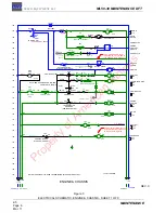
Figure 5

ELECTRICAL SCHEMATIC, LIFT & STAB. CONTROL - SHEET 3 OF 9

LIFT & STABILIZERS CONTROL

BODY DOWN

STABILIZER
EXTENDED

LOWER E-STOP

PENDANT E-STOP

(CLOSED WHEN EXT'D)

STABL. EXT'D

BODY UP

ENGINE STOP

R

BODY DOWN

LIFT MODE

LT6

STAB EXT'D

A

261

150

217

152

259

LIFT MODE

G

IP

IP

IP

LIFT POWER

[OPT.]

BODY UP

STABS

NOT STOWED

200 -

201 -

202 -

203 -

204 -

205 -

206 -

207 -

208 -

209 -

212 -

210 -

211 -

213 -

214 -

215 -

216 -

217 -

218 -

219 -

220 -

221 -

222 -

223 -

224 -

225 -

226 -

227 -

IGN

+12V

+12V

UC

GC

SW9

SW10-B

221

- 12V

- 12V

GC5

GC6

PC7

PC8

LT7

LT8

SW10-A

UC

UPPER E-STOP

UC7

UCS8

UCS7

PC8

UC8

219
125

STABILIZER
STOWED

STABL. STOWED

PS5

ST

1

3

2

(CLOSED WHEN STOWED)

SC

PS7

(BODY DOWN)

1

3

2

ST

PS2

ST

PS2

200

ST

STABILIZER
STOWED

PS2

B ENGINE STOP

[OPT.]

OVERRIDE [OPT]

STABL. EXT'D

STABL. EXT'D

STABL. EXT'D

[OPT. MULTIPLE STABILIZER SWITCHES]

STABL. STOWED

LS6-A

LS6-B

LS6-C

113

IP

ST

ST

ST

SW11

E

CC1-D

[OPT.]

105

OPT. +12V LIFT SIGNAL
FOR HIGH THROTTLE
FOR CHASSIS OTHER
THAN FORD

STABL. STOWED

PS5-A

ST

1

3

2

PS5-B

PS5-C

ST

ST

1

3

2

1

3

2

PS5-B

PS5-C

ST

ST

1

3

2

1

3

2

30

CR4

87A 

30

R13

87

8

6

CR4

CR6

(BRAKE SET)

85

86

CR7

R15

R16

R16

4

1

(NEUTRAL)

(NEUTRAL)

STABL. EXT'D

(BODY DOWN)

CB3

20A

LIFT CONTROL

LIFT MODE

86

85

R14

(STABS STOWED)

118

120

118

213

207

MB

MB

MB

MB

(LIFT MODE)

30

87

CR6

203

MB

MB

MB

MB

D2

D3

D4

R12 114

(ENGINE RUNNING)

IGN

LIFT

MODE

7

2

7

2

1

4

8

6

IGN

IGN

IGN

IGN

17

18

J16

18

17A

17

37

21

37

22

22

23

24

LIFT

25

26

27

27

27

BODY DOWN

BODY DOWN

IGN

IGN

+12V

MAIN BOX

LIFT

21

23

24

25

26

27

19

J8

J15

J9

R14

STABL. STOWED

MB

7

2

20

20

IGN

86

STABL. STOWED

85

CR13

[ENG. STOP OPT.]

MB

30

CR13

87A 

(STAB STOWED)

205

36

17B

17B

17C

30

CR14

87A 

(STAB STOWED)

109

7

CHASSIS

Black

Red

Orange/Blk

Orange/Red

Blue/Blk

Blue/Red

Black

Black/Red

Brown (4)

Blue (4)

Brown

Rh/Wht

Gr/Ylw

Rd/Blk

Black

Black

0.2A

0.2A

0.4A

0.4A

1.5A

1.5A

1.5A

13.2A

13.2A

4.5A

1.5A

1.5A

0.4A

0.2A

Mar. 17

Property of American Airlines

Summary of Contents for ML50-30

Page 1: ...MAINTENANCE LIFT Maintenance Manual Manufactured by TISl D TE co EQUIPMENT LLC Coral Springs Florida P r o p e r t y o f A m e r i c a n A i r l i n e s...

Page 2: ...ERSING PLATFORM VALVE 4 Flow Control Valve 4 COUNTER BALANCE HOLDING VALVE HOLD PRESSURE ADJUSTMENT 5 LIFT DOWN FLOW CONTROL VALVE ADJUSTMENT 6 Section 3 Troubleshooting GENERAL INFORMATION 1 INTRODUC...

Page 3: ...ol Sheet 3 of 9 Figure 5 1 Electrical Schematic Lift Stab Control Sheet 4 of 9 Figure 6 1 Electrical Schematic Options Sheet 5 of 9 Figure 7 1 Electrical Schematic Options Sheet 6 of 9 Figure 8 1 Elec...

Page 4: ...RACKS AND BOOSTER ARM UPPER LIP Page 10 2 1 Figure 10 OIL POINTS Page 11 Section 2 Hydraulic System Adjustments 2 2 Figure 1 HYDRAULIC SYSTEM Page 3 2 2 Figure 2 TRAVERSING PLATFORM VALVE Page 4 2 2 F...

Page 5: ...OF 9 Page 10 2 5 Figure 8 ELECTRICAL SCHEMATIC OPTIONS SHEET 6 OF 9 Page 11 2 5 Figure 9 ELECTRICAL SCHEMATIC OPTIONS SHEET 7 OF 9 Page 12 2 5 Figure 10 ELECTRICAL SCHEMATIC TABLES OF VEH CONNECTIONS...

Page 6: ...fluid leaks X Check spotlights indicator lights and beacon lights X Check hydraulic oil level X Check condition of all handrails and mounting brackets X Check condition of operator s boarding steps X...

Page 7: ...aulic oil expands when heated 1 The hydraulic oil reservoir is equipped with a sight gauge Ensure that the Hi Lift is fully lowered and stabilizers must be in stowed position when checking hydraulic o...

Page 8: ...an uncontaminated oil filtered to 10M Add the quantity of oil determined in step 2 8 Secure cap when finished 9 Recheck hydraulic oil level Figure 1 HYDRAULIC OIL FILL POINT 5 LUBRICATION A Grease Poi...

Page 9: ...ons check at more frequent intervals GREASE POINTS ITEM COMPONENT TOTAL FITTINGS INTERVAL 1 Scissor pivot pins Upper Middle Lower 12 6 mos 2 Scissor Arm End Pins 4 6 mos 3 Scissor roller Upper Lower 8...

Page 10: ...MAINTENANCE PROP BEFORE ACCESSING THE GREASE POINTS Figure 2 GREASE POINTS DIAGRAM Ref Figure 7 Ref Figure 8 Ref Figure 7 Ref Figure 6 Ref Figure 3 1 3 6 7 1 5 1 3 2 4 5 Ref Figure 3 Figure 4 Ref Figu...

Page 11: ...OINTS LIFT CYLINDERS UPPER TOP LIFT CYLINDER BOTTOM LIFT CYLINDER 1 Set the maintenance prop Refer to Chapter 1 2 2 Raise or lower the lift to access all grease points of upper lift cylinder rollers 4...

Page 12: ...TESCO EQUIPMENT LLC Figure 4 GREASE POINTS LIFT CYLINDERS BOTTOM Figure 5 GREASE POINTS STABILIZERS TOP LIFT CYLINDER BOTTOM LIFT CYLINDER GREASE POINT GREASE POINT GREASE POINT 4 PER LEG Mar 17 P r o...

Page 13: ...ML50 30 MAINTENANCE LIFT Figure 6 GREASE POINTS TRAVERSING CYLINDER AND ROLLERS GREASE POINT TRAVERSING CYLINDER ROD ENDS BOTH ENDS GREASE POINT BOTH ENDS TRAVERSING ROLLER PINS 8 PLCS Mar 17 P r o p...

Page 14: ...PINS SCISSOR PIVOT PINS BOTH SIDES UPPER AND LOWER SCISSOR ARM END PINS 4 PLCS SCISSOR CENTER PINS BOTH SIDES UPPER AND LOWER UPPER SCISSOR ROLLERS BOTH SIDES SCISSOR LOWER ROLLER PINS BOTH SIDES NOTE...

Page 15: ...NANCE LIFT Figure 8 GREASE POINT LOWER BOOSTER ARM Figure 9 GREASE POINTS TRACKS AND BOOSTER ARM UPPER LIP GREASE POINT GREASE W BRUSH SCISSOR ROLLER TRACKS BOTH SIDES UPPER AND LOWER BOOSTER ARM LIP...

Page 16: ...NENT TOTAL PLCS INTERVAL 1 Lift Cylinder Rods 4 6 mos 2 Platform entry swing gate hinge points Lock 3 1 mos 3 Platform Ext Segments Pocket Locking Bar 1 mos OIL NOTE Use SAE 5W 30W oil or other adequa...

Page 17: ...THIS PAGE INTENTIONALLY LEFT BLANK P r o p e r t y o f A m e r i c a n A i r l i n e s...

Page 18: ...ETS ON THE SKIN WASH AFFECTED AREA IMMEDIATELY TO AVOID IRRITATION WARNING DRIVE WHEELS MUST BE CHOCKED TO PREVENT MOVEMENT OF THE UNIT IN EITHER DIRECTION WARNING WHEN MAKING PRESSURE CHECKS OR ADJUS...

Page 19: ...Loosen locknut and turn valve clockwise to slow lift speed counter clockwise to increase lift speed Tighten locknut when adjustment is complete C Main Relief 1800 psi 25 With the engine running exten...

Page 20: ...etract stabilizers between adjustments Chassis must be level 1 in 2 54 am side to side Ensure Stabilizer Pressure Switch still just activates when stabilizers are extended Screw in adjustment to incre...

Page 21: ...HYDRAULIC ADJUSTMENTS TRAVERSING PLATFORM VALVE A Flow Control Valve 1 Loosen locknut A 2 Turn clockwise to to slow down and counter clockwise to speed up 3 Tigntened locknut Figure 2 TRAVERSING PLATF...

Page 22: ...y and backing out one and three quarter 1 3 4 turns for 1400 PSI setting 1 Extend stabilizer cylinders and partially raise lift Install maintenance prop NOTE Adjust one counterbalance valve at a time...

Page 23: ...e down together The lowering speed may be adjusted to increase or decrease the hi lift s lowering speed 1 Raise the scissor to the maximum height 2 Activate lift down function and record the time it t...

Page 24: ...ded as a guide to assist technical service personnel in troubleshooting operational malfunctions in the ML5 30 Lift Unit hydraulic and electrical systems 1 Before starting troubleshooting procedures v...

Page 25: ...gency operation the hand pump or optional electric auxiliary hydraulic pump may be used to provide hydraulic flow Press both UP switches simultaneously if not equipped with an ENABLE switch In this ca...

Page 26: ...d or blown fuse Defective solenoid coil or relay Damaged or defective control switch Damaged wiring or bad ground Damaged Power Take Off P T O or pump drive components Stabilizers will not hold retrac...

Page 27: ...pen Upper controls will not operate with the vehicle s engine running Vehicle not in lift mode Parking brake off Enable switch not depressed Stabilizers not fully deployed Emergency stop activated Cir...

Page 28: ...lve Hi lift unit racked or twisted in one direction during raising or after reaching required height Exceeding maximum load capacity Off center load on work platform Air trapped in lift cylinder Misad...

Page 29: ...ic oil viscosity too light for climate Hydraulic oil continuously flowing over relief valve Relief valve pressure is set too low or too high Worn pump or internal damage to pump Hydraulic oil pump is...

Page 30: ...595 Welded joint configuration and preparations must be in accordance with existing AWS DD1 1 welding code for structural welding 2 STRUCTURAL REPAIRS A Scissor arms Welded repairs on scissor arm s st...

Page 31: ...THIS PAGE INTENTIONALLY LEFT BLANK P r o p e r t y o f A m e r i c a n A i r l i n e s...

Page 32: ...Sheet 2 of 9 Figure 4 D Electrical Schematic Lift Stab Control Sheet 3 of 9 Figure 5 E Electrical Schematic Lift Stab Control Sheet 4 of 9 Figure 6 F Electrical Schematic Options Sheet 5 of 9 Figure 7...

Page 33: ...TRAVERSE CYLINDER FLOW CONTROL PLATFORM TRAVERSE VALVE DO3 TYPE VALVE N C CHECK MAIN MANIFOLD STRAINERS 6 16 6 8 1 8 NPT DO5 TYPE STABILIZER VALVE SOL3 750 3000 T P SOL4 PRESSURE REDUCER PRSBLAN ENGIN...

Page 34: ...Stabilizer 2 HYMS20041 VALVE D05 3 Pos 4 Way Lift Stabilizer 1 HYMS20055 MANIFOLD Sandwitch Port Relief 1 HYVA10247 CARTRIDGE Port Relief 1 HYMS20048 CARTRIDGE Lift Flow Control Valve 1 HYMS20045 GAUG...

Page 35: ...THIS PAGE INTENTIONALLY LEFT BLANK TESCO EQUIPMENT LLC ML50 30 MAINTENANCE LIFT MAINTENANCE 2 5 Page 4 Dec 06 P r o p e r t y o f A m e r i c a n A i r l i n e s...

Page 36: ...7 1 66 6 5 6 1 7 6 2 5 6 6 7 2 9 211 7 216 21 6 7 5 211 7 21 32 17 12 75 211 7 21 7 50 1 1 0 1 2 5 180 5 1 5 0 32 17 2 5 7 6 2 237 216 5 0 5 1 7 21 21 1 8 1 0 1 81 7 21 2 66 0 6625 81 2 1 66 6 2 7 21...

Page 37: ...UC 1 ON SW2 B 5 UCS10 7 UC 7 7 41 SW2 C SW2 UCS9 41 CC3 ENGINE RESTART J10 UC9 J11 UC10 J1 UCS 1 J2 UCS 2 UC2 12 VOLT ENABLE 2 3 3 200 RESTART 200 ENGINE STOP OPT B A REVERSE FLOOD OPT 153 CC1 D E OPT...

Page 38: ...3 174 175 176 IGN 12V 12V 12V HEADLIGHT SWITCH SW3 FLASHER BEACON SW7 LIGHTING 13 14 15 16 15A GC7 15 35 40 15A L X P MB J13 J7 PLATFORM WORK LIGHTS SW6 LIGHTS 2 PLATFORM WORK BP WORK LIGHTS LT3 2 CB2...

Page 39: ...A LS6 B LS6 C 113 IP ST ST ST SW11 E CC1 D OPT 105 OPT 12V LIFT SIGNAL FOR HIGH THROTTLE FOR CHASSIS OTHER THAN FORD STABL STOWED PS5 A ST 1 3 2 PS5 B PS5 C ST ST 1 3 2 1 3 2 PS5 B PS5 C ST ST 1 3 2...

Page 40: ...RETRACTED LS15 BP 1 3 2 PLAT RETRACTED 265 PLAT RETRACTED 302 273 G 273 G OPT LIFT W O STABL S OPEN HEIGHT LS15 BP 9 S1 S2 315 F 321 G 320 F 319 E STABL S EXTENDED CR7 ALL MOTION ALARM OPT BODY DOWN...

Page 41: ...LATF EXT SOL9 PLATF RETR SOL10 ELECTRIC CON1 ELECT CON1 HYDRAULIC HYDRAULIC PUMP PUMP MB MB CC CC MV EXTEND RETRACT PLATFORM PC 1 PC 2 EXTEND 0 RETRACT 310 SW21 SW21 A SW21 B SW23 M1 PC 3 PC 3 HYDR PU...

Page 42: ...W5 SW7 REVERSE FLOOD A 107 SW5 A SW5 B 15 16 15 35 40 152 153 154 155 156 157 158 159 15 15A 41 FLASHER L X P MB 35 40 7 UC 1 UC 2 HOUR METER STOP ENGINE STOP 104 110 102 7 3 WAY SWITCHES OPT IGNITION...

Page 43: ...CR20 GROUND POWER CONNECTED GROUND POWER CONNECTED R LTX CR20 125 GP IP GROUND POWER WARNING LIGHT 217 GROUND POWER 315 316 120VAC WHEN GROUND POWER CONNECTED CR20 GROUND POWER CONNECTED 316 217 316...

Page 44: ...STEM SCHEMATICS 2 5 Page 13 ML50 30 MAINTENANCE LIFT TESCO EQUIPMENT LLC Figure 10 ELECTRICAL SCHEMATIC TABLES OF VEH CONNECTIONS SHEET 8 OF 9 Mar 17 P r o p e r t y o f A m e r i c a n A i r l i n e...

Page 45: ...E 2 5 Page 14 TESCO EQUIPMENT LLC ML50 30 MAINTENANCE LIFT Figure 11 ELECTRICAL SCHEMATIC TABLES OF VEH CONNECTIONS DPDT SPDT RELAY WIRING SHEET 9 OF 9 Mar 17 P r o p e r t y o f A m e r i c a n A i r...

Reviews: