2
•
INPUT
o
IGBT rectifier type input PFC correction
o
PI controlled PFC circuit
o
Fuse protected input
o
Adjustable mains failure limit
o
Adjustable mains high limit (switching tobattery option)
•
BYPASS
o
Static bypass system
o
Split bypass input (OPTIONAL)
o
Voltage adaptive load transfer system
o
Adjustable bypass input voltage limits
o
Adjustable frequency synchronization band
o
Maintenance bypass switch (OPTIONAL)
•
BATTERY
o
Flexible battery quantity
o
Battery remaining time indicator
o
Fuse protected battery group
o
Adjustable battery charging current limit
o
Total battery voltage high protection
o
3 level battery alarm and warning
o
Battery deep discharge protection
o
Boost and float battery charger modes
o
Automatic or manual battery test function (user selectable)
o
Internal batteries
o
Automatic or manual restart selection after battery autonomy end
o
Temperature compensation for battery charging
•
OUTPUT
o
3 level overload protection
o
Output current limit (on or off selectable)
o
Output fuse protection
o
PID control in output voltage regulation
o
Isolated short circuit protection from bypass input
o
Adjustable output voltage low and high protection
•
COMMUNICATION and INTERFACE
o
RS232 interface
o
Interactive control command protection
o
NO or NC selectable DRY contacts (standard line failure ,battery low and bypass)
o
OPTIONAL programmable relay outputs (AUX1 and AUX2 contacts NO or NC selectable)
o
Digital input (OPTIONAL)
o
REPO-External remote emergency power off input (NO-NC programmable)
o
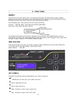
LCD front panel ,5 buttons ,indicator lamps and buzzer on front panel
o
SNMP adaptor for communication (OPTIONAL)
o
RS232 serial port multiplexer (OPTIONAL)
o
Modbus adaptor (OPTIONAL)
o
128 events (5000 alarms) logging with time and date
o
RTC clock (separate battery supported)
o
Relay simulation from front panel and RS232
o
Operation hour-meter
o
Service time indicator
o
Front panel language selection
o
Front panel lamp test function
o
Input voltage and frequency ,bypass voltage and frequency ,output voltage and
frequency ,cabinet inside temperature ,load percentage ,load current ,battery voltage
and current measurements
Summary of Contents for CL115D Series
Page 1: ...UPS USER MANUAL CL115D...
Page 4: ...AGKK9530 01 2011...
Page 37: ...33...
Page 38: ...34 AGKK9530 06 2014...


