5
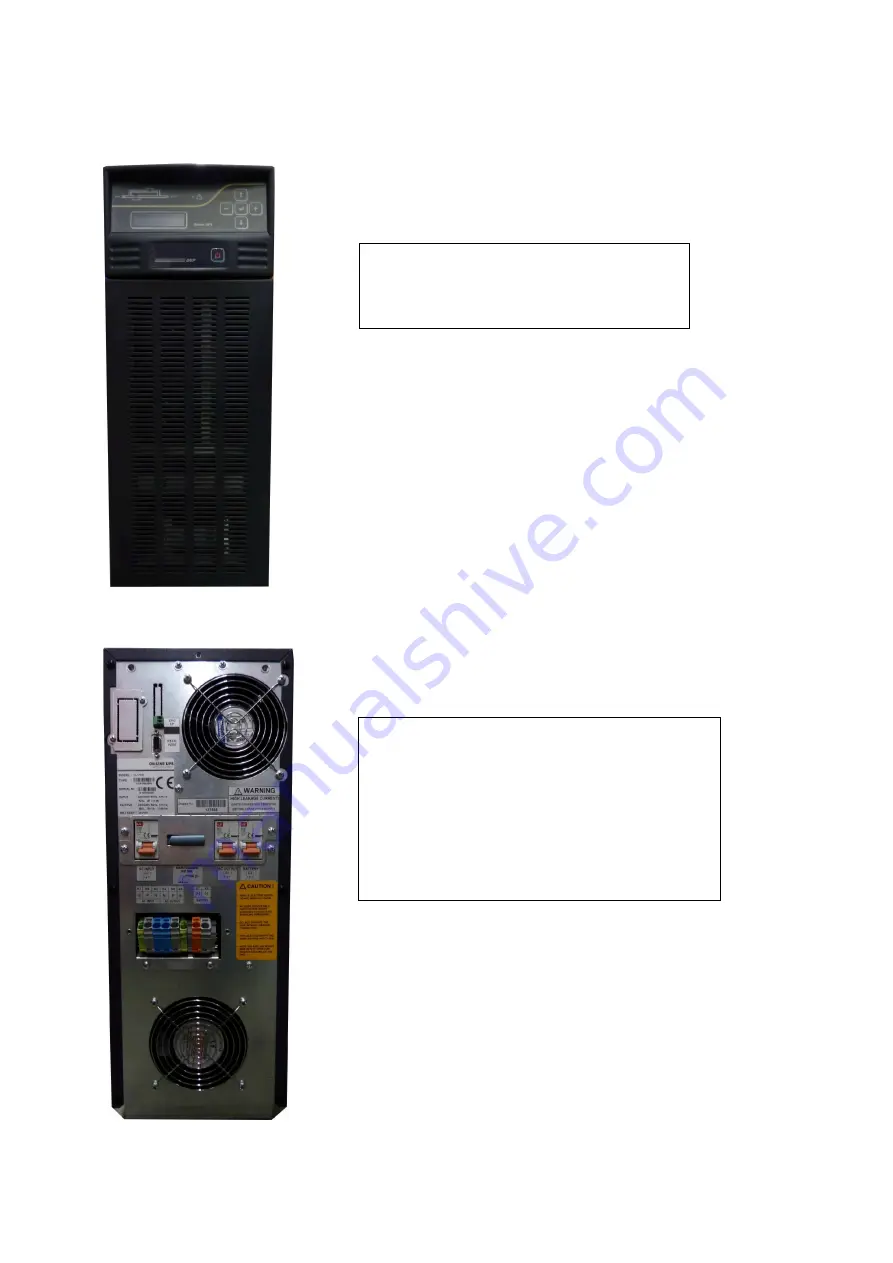
Front view of the UPS
1) Cooling inlet of the UPS
2) Control panel
3) Power on/off button
Rear view of the UPS
4) Emergency Stop
5) SNMP Socket
6) RS232 communication port
7) Cooling outlet of the UPS
8) Output switch/fuse (S1)
9) Input switch/fuse (S2)
10) Battery switch/fuse (S3)
11) Maintenance bypass switch (SW5)
12) Input, output and battery screw terminals
2
3
1
9
7
10
8
11
12
5
4
6
Summary of Contents for CL115D Series
Page 1: ...UPS USER MANUAL CL115D...
Page 4: ...AGKK9530 01 2011...
Page 37: ...33...
Page 38: ...34 AGKK9530 06 2014...


