50
Note:
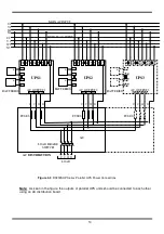
As seen in the figure, the outputs of parallel UPS units should be connected to each other
using an AC distribution board.
Figure 4.3
DS300SHP Series Parallel UPS Power Connections
BATTERIES
U V W N
LOAD
FUSES
AC
BYPASS AC INPUT
MAIN AC INPUT
AC DISTRIBUTION
U1
V1
W1
N1
U2
V2
W2
N2
+
-
+
-
UPS1
K3
K2
K2
K
4
K
5
K
6
K
7
K
8
K
9
K
1
0
K
1
1
K12 K13 K14
K1
U V W N
AC OUTPUT1
+
-
+
-
BATTERIES
UPS2
K3
K2
K2
K
4
K
5
K
6
K
7
K
8
K
9
K
1
0
K
1
1
K12 K13 K14
K1
U V W N
AC OUTPUT2
FUSES
+
-
+
-
BATTERIES
UPS3
K3
K2
K2
K
4
K
5
K
6
K
7
K
8
K
9
K
1
0
K
1
1
K12 K13 K14
K1
U V W N
AC OUTPUT3
FUSES
LOAD BRAKE
SWITCH
Summary of Contents for DS300SHP Series
Page 1: ...DS300SHP SERIES DSP Controlled UPS 10 15 20 kVA 3 Phase IN 3 Phase OUT USER MANUAL...
Page 2: ......
Page 17: ...15 Figure 2 3 External Battery Connections 60x12V 30x12V Batteries 30x12V Batteries...
Page 18: ...16 Figure 2 3a DS300SHP Series 10 15 20 KVA Internal Battery Connections 60x12V 5Ah...
Page 19: ...17 Figure 2 3a DS300SHP Series 10 15 20 KVA Internal Battery Connections 60x12V 7 9Ah...
Page 70: ......
Page 71: ...AGKK12630 04 2017...


