9
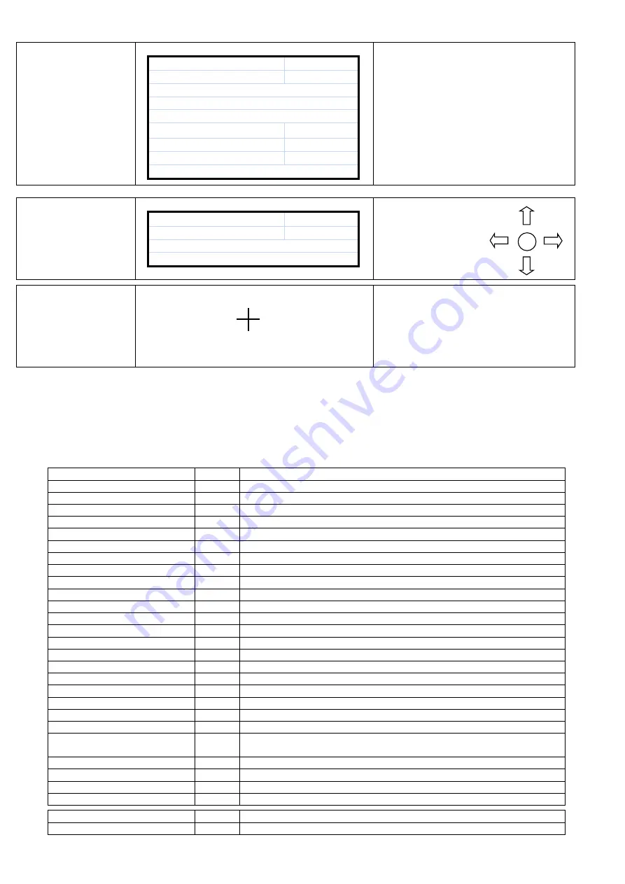
SERVICE MENU
HOURMETER :
!!!
ENTER<FAULT RESET> :
!!!
------------------------------------------------------
------------------------------------------------------
------------------------------------------------------
LOGOUT
…
. : OK
RELAY CONTACTS :
!!!
ENTER
EXIT
-------- Alarm Line --------
Ones other than total working hour data are
only used for monitoring.
ADJUST MENU
SERV. PASS :
!!!
USER PASW :
!!!
-------- Alarm Line --------
Made through UPS except
main panel settings.
T.CALIB MENU
TOUCH THE STATED POINTS FOR CALIBRATION
TOUCH SCREEN CALIBRATION SETTING IS
DONE.
CLICK ON THE CENTER OF PLUSES
AUTOMATICALLY INDICATED FOR
CALIBRATION.
Lowest line is the alarm indicator.
3.3 UPS status information and alarm messages (Lower line)
Alarm line shall be seen as empty on the LCD screen when no alarm or event is available. Alarms indicated on the
screen vary depending on UPS communication protocols. Alarms to be monitored depending on TX300 and TX301
protocols are indicated in below given tables.
TX301 protocol alarm and statuses
REC CODE = 1XXX
Status code of rectifier module at that moment.
R00 PFC ERROR = XXXX
Error
System error in PFC Module XXXX value indicates the occurring error.
Call the service
R01 AC INPUT HIGH
Alarm
Rectifier AC input voltage high, rectifier stopped
R02 GRID INTERRUPTED
Alarm
Rectifier AC input voltage interrupted, rectifier stopped
R03 DC HIGH
Alarm
Rectifier DC output voltage high, rectifier stopped
R04 DC LOW
Alarm
Rectifier DC output voltage low, rectifier stopped
R05 FREQ TOLER
Alarm
Rectifier AC input frequency out of tolerance, rectifier stopped
R06 OVER HEAT
Alarm
Excessive heating at rectifier power cooler, rectifier stopped
R07 SHORT INTERRUPTION
Alarm
Short term interruption at rectifier input voltage, rectifier stopped
R08 IGBT ERROR
Alarm
Excessive load at rectifier power components, rectifier stopped
R09 PHASE ROTATE
Alarm
Rectifier AC input voltage phase line faulty, rectifier stopped
R14 PFC PAUSED
Alarm
Rectifier paused for short period
R15 DC LOW
Alarm
DC busbar reduced while rectifier operates, rectifier shall start again after 20 seconds.
R17 ACCUMULATOR TEST
Warning
Accumulator test is in progress (lasts for 30 seconds)
R18 BOOST CHARGE
Warning
Rectified charge is in progress (lasts for 10 hours)
R19 AC HIGH
AC input peak voltage 20% higher
R20 INPUT CONTACTOR
Warning
Input contactor is in released status
R21 PFC STOPPED
Warning
Rectifier stopped for short period by the inverter module
R22 POS CHARGE LIMIT
Warning
(+)Accumulator charge current limited
R23 NEG CHARGE LIMIT
Warning
(-)Accumulator charge current limited
R24 DC BUSBAR HOLD
Warning
Rectifier waits for DC busbar increase to start
R25 ACCUMULATOR FAILURE
Warning
Accumulators found faulty in the accumulator test
R26 ACCUMULATOR HEAT
SENSOR
Warning
Accumulator heat sensor failed or not plugged.
R27 ACCUMULATOR HEAT HIGH
Warning
Accumulator environment heat is high
R28 PHASE LOSS
Warning
Missing phase in input.
R29 PFC RESET
Warning
PFC module supply applied recently (only seen when the device is started for the first time)
R30 WAIT !
Warning
Rectifier start delay waits for the setting period.
L01 TH1 HIGH HEAT
Warning
TH1 heat sensor heat is higher than the adjusted alarm level
L02 TH2 HIGH HEAT
Warning
TH2 heat sensor heat is higher than the adjusted alarm level
Summary of Contents for RM2020
Page 1: ...0 UPS REMOTE MONITORING PANEL RMP X1 INSTALLATION AND USER S GUIDE ...
Page 14: ...13 ...
Page 15: ...14 AGKK13150 08 2018 ...


