background image


2.2 

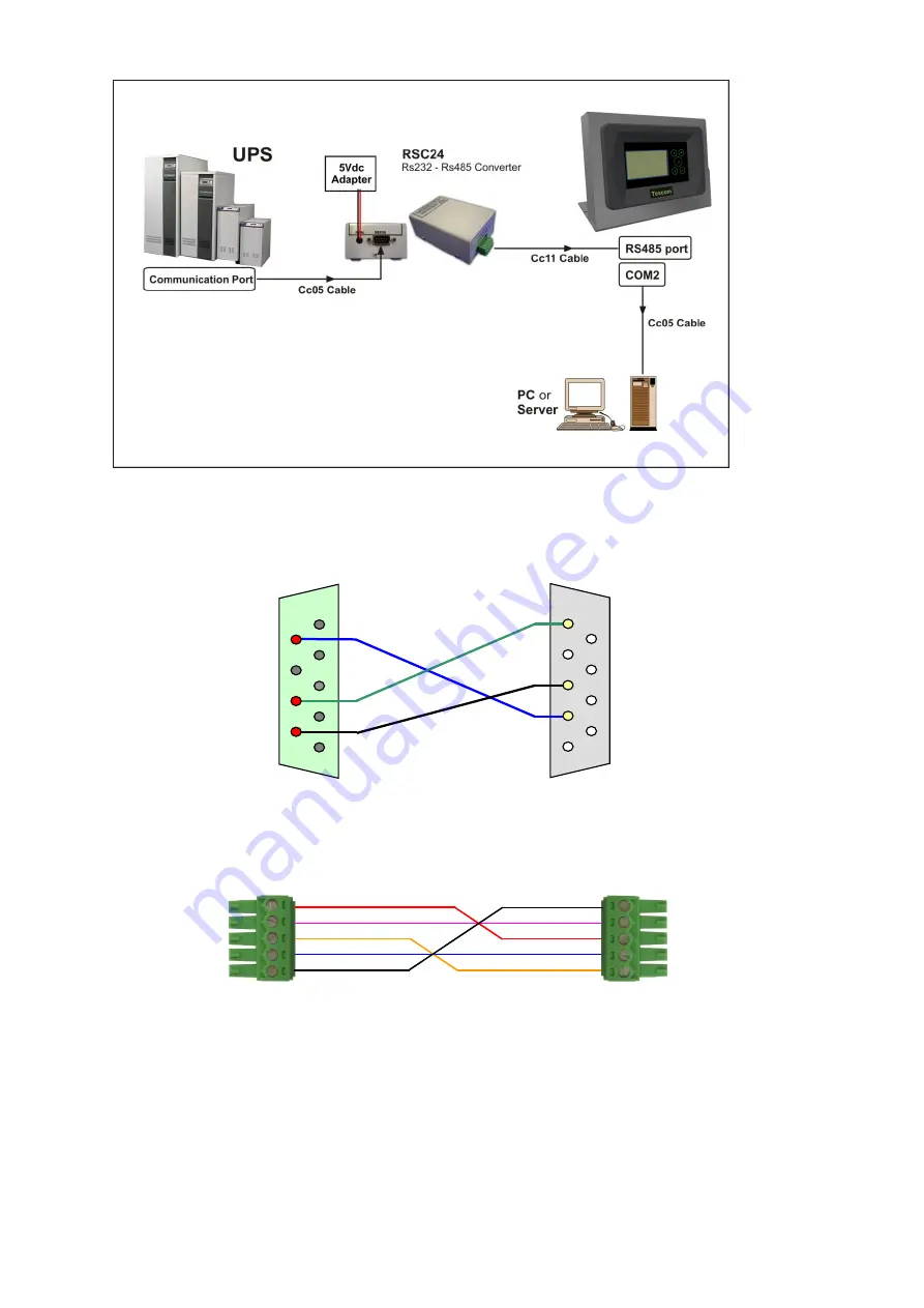
Explanations on Cable pin between UPS - Remote monitoring panel  


CC05 RS232 communication cable (max. 25m) 


CC11 RS485 communication cable (distances further than 25m) 


RMP COM1  
or  
PC (COM PORTS) 

4


3


5


2


1


8


7


4


1


8


7


6


2


9


6


9


5


3


UPS 
communication 
port or  
RMP COM2 

CONNECTOR 
MC1.5/5-ST-3.81 

 RMP 

RS485 input 

 PORT 

Tx- 
Tx+ 
Rx- 
Rx+ 

Gnd 

Gnd 

Tx- 

Tx+ 

Rx- 

Rx+ 

CONNECTOR 
MC1.5/5-ST-3.81 

 RSC24 

RS485 

output  

 PORT 

RMP-X1 

Summary of Contents for RM2020

Page 1: ...0 UPS REMOTE MONITORING PANEL RMP X1 INSTALLATION AND USER S GUIDE ...

Page 2: ...RESENTATION 2 1 1 Package Opening and Content Control 2 1 2 View of Remote Monitoring Panel 2 1 3 Functions 2 1 4 Front panel functions 3 1 5 Technical Characteristics 3 2 INSTALLATION 4 2 1 UPS and Remote Monitoring Panel connection types 4 2 2 Explanations on Cable pin between UPS Remote monitoring panel 5 2 3 Mechanical Installation 6 2 4 Before Starting 6 3 STARTING 6 3 1 LCD Menu Structure 6 ...

Page 3: ...an be connected through RS232 and RS485 communication networks It has separate input port for each communication network It has communication output port equal to UPS communication port It can transmit responses coming from UPS to other devices from this port with RS232 Device has 3 relay outputs dry contact Views and functions of ports are as given below 5V DC Supply input RS485 input Port TX TX ...

Page 4: ...ter OK button Used for entering the selected menu or confirming the selected option 1 5 Technical Features Function Parameter Value COM1 RS232 UPS Port Baud rate 2400 baud Parity No parity Stop bit 1 stop bit UPS Connection RXD TXD Gnd 3 wire Pin no Function 1 Empty 2 TXD RS232 3 RXD RS232 4 Empty 5 Signal Ground 6 Empty 7 Empty 8 Empty 9 Empty TFT Screen Enter OK button Selection buttons ...

Page 5: ...stance Connection shall be made with CC05 coded cable See the next topic for pin explanations of CC05 Cable RS485 connection This connection type is used for distances longer than 25 meters with UPS As UPS has standard RS232 communication output RSC24 model RS232 RS485 converter adapter should be used to establish communication with RMP Input of this adapter shall be established with CC05 coded ca...

Page 6: ...e max 25m CC11 RS485 communication cable distances further than 25m RMP COM1 or PC COM PORTS 4 3 5 2 1 8 7 4 1 8 7 6 2 9 6 9 5 3 UPS communication port or RMP COM2 CONNECTOR MC1 5 5 ST 3 81 RMP RS485 input PORT Tx Tx Rx Rx Gnd Gnd Tx Tx Rx Rx CONNECTOR MC1 5 5 ST 3 81 RSC24 RS485 output PORT RMP X1 ...

Page 7: ...easured parameters These menus can be roamed with the menu selection button and enter into menu content with the enter button Menu selection button is used again to monitor different parameters inside the menu Menu names and monitorable values are given at upper line on the LCD screen UPS status information and alarms are monitored on the lower line Values in the menu content vary depending on com...

Page 8: ... P P L1 3 L2 1 L3 2 V V FREQ Hz Alarm Line BYPASS VOLTAGE VALUES BETWEEN PHASE NEUTRAL BYPASS VOLTAGE VALUES BETWEEN PHASE PHASE BYPASS FREQUENCY STATUS AND VALUE LOWEST LINE IS THE ALARM INDICATOR MEASURES INVERTER P N L1 L2 L3 V V Alarm Line INDICATES THE INTERTER VOLTAGE VALUES BETWEEN PHASE NEUTRAL LOWEST LINE IS THE ALARM INDICATOR MEASURES OUTPUT P N L1 L2 L3 V V I A P P L1 3 L2 1 L3 2 V V F...

Page 9: ... setting and Button volume setting screen background illumination settings are adjusted independent from UPS Lowest line is the alarm indicator Remote control permission setting UPS communication frequency setting 2400 9600 UPS communication type setting RS232 RS485 Setting for alarm assignment to internal alarm relays Selection screen indicates the normal open or closed emergency stop button inpu...

Page 10: ...stopped R07 SHORT INTERRUPTION Alarm Short term interruption at rectifier input voltage rectifier stopped R08 IGBT ERROR Alarm Excessive load at rectifier power components rectifier stopped R09 PHASE ROTATE Alarm Rectifier AC input voltage phase line faulty rectifier stopped R14 PFC PAUSED Alarm Rectifier paused for short period R15 DC LOW Alarm DC busbar reduced while rectifier operates rectifier...

Page 11: ...ing device will stop soon and electricity of connected loads will be interrupted A27 GENERATOR MODE Warning Device operates at generator position A28 PHASE LOSS Warning Interruption in any of phases at UPS output A29 NO SYNCHRON Warning Inverter is not synchronous to by pass input A30 SHORT CIRCUIT Warning Short circuit occurred and passed at UPS output A31 OUTPUT SWITCH Warning Device output swit...

Page 12: ...pplied operation period will be short User will be warned with an audio warning once in 15 seconds when this message is seen A19 BATT FAULT Accumulators are detected as faulty as the result of accumulator test Message may be deleted by the user by pressing the enter button for 3 seconds User will be warned with an audio warning once in 15 seconds when this message is seen A20 BOOST CHARGE Accumula...

Page 13: ... a different alarm occurs panel voice will be opened automatically 4 POSSIBLE FAILURES If electricity is not supplied to panel when the supply cable is plugged supply cable may be failed The socket which the cable is plugged in may be failed Main card transformer of remote monitoring panel may be failed All connections made with UPS but if communication interrupted alarm is given on the remote mon...

Page 14: ...13 ...

Page 15: ...14 AGKK13150 08 2018 ...

Reviews: