ALUMINIUM PIPEWORK - ALUMINIUM PIPEWORK - ALUMINIUM PIPEWORK - ALUMINIUM PIPEWORK - ALUMINIUM PIPEWORK - ALUMINIUM PIPEWORK
98
FLUID POWER DISTRIBUTION SYSTEMS - FLUID POWER DISTRIBUTION SYSTEMS - FLUID POWER DISTRIBUTION SYSTEMS - FLUID POWER DISTRIBUTION SYSTEMS - FLUID POWER DISTRIBUTION SYSTEMS
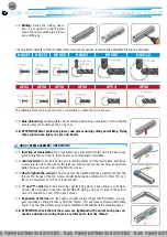
3.5. Hole de-burring: on outlet plates we recommend de-burring a maximum 1mm around the
hole in order not to damage the o ring seal.
3.6. ATTENTION: Wear protective glasses and gloves during cutting and drilling. Flying
chips could cause injury to eyes and hands.
The following tools can be used: a drill, a coned drill, a counter bore, a hole saw.
The maximum diameter of the smoothed hole must not exceed the recommended diameter. Please see the table.
3.4. Drilling: during the drilling opera-
tion, it is required to have the pilot
hole in the centre of the pipe. Please
use a drilling jig.
4. HBS SYSTEM ASSEMBLY OPERATIONS
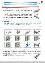
4.1. Insertion of small plates: the small plates can be inserted into the slot in the bar at any
point. Straighten and secure them by means of sharpened small tubes.
4.2. Joint insertion: to make it easier, first insert the plates and the small plates with loose
screws into the slots, then insert the joint and connect the second bar. Now position the
plates half-way on each side and tighten the screws.
4.3. How to tighten the screws: The screws must be tightened but be careful not to tear the
thread. The torque of the m6 screws should be between a minimum of 10 N·m (91 inch-
lbs) and a maximum of 13.5 N·m (120 inch-lbs).
4.4. “L” and “T” Joint have to be fixed using specific fixing plates. They allow you to fix pipes
on two sides. Should you need to connect HBS 25 piping, using an “L” joint on the narrow
side, it is required to cut 6 mm on each corner.
4.5. Expansion of the line: for lines with a straight section longer than 50 meters, we sug-
gest mounting a sliding joint every 30 to 40 meters. This will make any future dismantling
easier. The two fixing plates have to be assembled in the middle of the available space.
4.6. ATTENTION: check that all the screws are tightened at the end of each pipe con-
nection and when securing them be careful not to tear the thread.
AP22
AP28
AP36
AP45
AP54
AP68
HBS25
HBS32
HBS50
HBS63
HBS80
HBS110


