background image

ALUMINIUM PIPEWORK - ALUMINIUM PIPEWORK - ALUMINIUM PIPEWORK - ALUMINIUM PIPEWORK - ALUMINIUM PIPEWORK - ALUMINIUM PIPEWORK

101

FLUID POWER DISTRIBUTION SYSTEMS - FLUID POWER DISTRIBUTION SYSTEMS - FLUID POWER DISTRIBUTION SYSTEMS - FLUID POWER DISTRIBUTION SYSTEMS - FLUID POWER DISTRIBUTION SYSTEMS

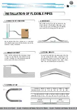
We remind you that to avoid any distortion, the 

bend radiuses of the flexible rubber pipes must 

not be too sharp to avoid damage it, the flexible 

pipe mustn’t be forced against the obstacle.

Hoses can be useful when the changing of level 

is lower or equal than the encumbrance of two 

L Joints; However it is recommended when the 

vertical side of the line can’t be fixed.

It is useful too when the horizontal angle of the line 

can’t be achieved with others components from 

our catalogue; however it remains possible to use 

terminals threaded together from steel compo-

nents (not recommended) from retail trade.

2. OBSTACLES

5. CURVING AT 180°

I

NSTALLATION OF FLEXIBLE PIPES

1. CONNECTION TO MACHINE

3. CHANGES IN HEIGHT 

4. SPECIAL ANGLES

Material

EPDM

Temperature

-30°C ÷ +70°C

Available for special request

We recommend that the compressor is connected 

with a flexible pipe to absorb the vibrations due to the 

machine on every installation.

Flex Pipe

HBS25

HBS32

HBS50

HBS63

HBS80

Min Radius mm

100

130

200

270

340

Flex Pipe

AP22

AP28

AP36

AP45

AP54 

AP68

Min Radius mm

90

100

130

150

200

270

Summary of Contents for HBS-AP

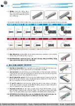
Page 1: ...could clog the tool When making many cuts we suggest using a circular chop saw with metal cutting blade 3 2 Deburring after cutting the pipe it is necessa ry to remove the sharp edges using a de burring tool This operation is required to avoid any da mage to the o ring and to make easier the con nection 2 TOOLS AND FIXTURES 2 1 The tools required to install even a small system are one Allen wrench...

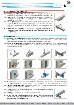
Page 2: ... to make it easier first insert the plates and the small plates with loose screws into the slots then insert the joint and connect the second bar Now position the plates half way on each side and tighten the screws 4 3 How to tighten the screws The screws must be tightened but be careful not to tear the thread The torque of the m6 screws should be between a minimum of 10 N m 91 inch lbs and a maxi...

Page 3: ...th clamping brackets to touch the profiles and tighten the screws 5 2 Joints introduce the joint into one pipe then connect the second pipe position the clamping bracket equally so that it is clamping both pipes or fitting and half the other and finally tighten the screws 5 3 Screws tightening Screws must be tightened properly but not excessively to avoid stripping the threads The recommended tigh...

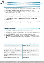
Page 4: ... contact our technical department 8 4 ATTENTION release pressure from the area of the system to be modified before carrying out re pairs maintenance or modifications Isolate the area and inform people about maintenance opera tions 7 GENERAL TEST AND INSPECTION 7 1 Inspect every part of the system and check that no screw is loose that all joints are properly in place and all brackets are properly s...

Page 5: ...ed It is useful too when the horizontal angle of the line can t be achieved with others components from our catalogue however it remains possible to use terminals threaded together from steel compo nents not recommended from retail trade 2 OBSTACLES 5 CURVING AT 180 INSTALLATION OF FLEXIBLE PIPES 1 CONNECTION TO MACHINE 3 CHANGES IN HEIGHT 4 SPECIAL ANGLES Material EPDM Temperature 30 C 70 C Avail...

Reviews: