background image

Druck DPI 811/812

RTD calibrator and 
RTD loop calibrator

User manual - K345

99 Washington Street 

Melrose, MA 02176 

Phone

 781-665-

1400

Toll Free 1-800-5

17

-8431

Visit us at www.T

estEquipmentDepot.com

Summary of Contents for Druck DPI 811

Page 1: ...Druck DPI 811 812 RTD calibrator and RTD loop calibrator User manual K345 99 Washington Street Melrose MA 02176 Phone 781 665 1400 Toll Free 1 800 517 8431 Visit us at www TestEquipmentDepot com...

Page 2: ...K345 Issue 4 A1 A2 DPI 812 A3 10 1 3 4 2 5 6 7 9 8 A2 A3 11 B1 12 10 14 15 13 20 21 22 25 17 18 26 19 27 16 23 24 B1 Customer service Visit our web site www gesensing com...

Page 3: ...s uses Intelligent Digital Output Sensor IDOS technology to give instant plug and play functionality with a range of Universal Measurement Modules UMM Example the Universal Pressure Module UPM The DPI...

Page 4: ...ion above it on the display Item 25 Example Settings 8 Display Refer to A3 9 SENSOR PC Communications port Use to connect a Universal Measurement Module UMM or a RS232 cable 10 RTD connectors To measu...

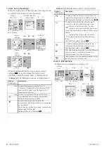
Page 5: ...se this instrument together with a HART communicator to set up and calibrate HART devices Scale To select the applicable international temperature scale IPTS 68 or ITS 90 To select and set up the back...

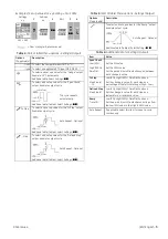
Page 6: ...select and set up a tare value for the measurement task a specified value or the reading on the display The instrument subtracts a positive tare value and adds a negative tare value Additional data S...

Page 7: ...ional Additional data Table 6 Select Settings Step To select and set up values for the Defined Step output Example output cycle Auto Repeat Optional Additional data Table 6 Select Settings Options If...

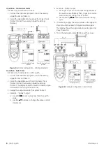
Page 8: ...adjust the Set Up Table 1 2 Select the RTD or Ohms input task from Select Task Table 2 3 and if necessary adjust the Settings Table 4 Figure 1 Example configuration To measure the temperature or resis...

Page 9: ...ransmitter calibration DPI 812 only To calibrate a transmitter 1 Connect the instrument Figure 3 4 and if necessary adjust the Set Up Table 1 2 Select the applicable calibration task from Select Task...

Page 10: ...the top right hand corner 3 Supply the output values to the system Table 7 Example Nudge output a Use Edit to set a value less than the switch value b Use the buttons to change the value in small incr...

Page 11: ...Settings Table 4 5 2 If necessary do a zero correction Table 4 To measure pressure with another operation Figure 8 use the same procedure Figure 8 Example configuration To measure pressure and temper...

Page 12: ...set the new calibration date for the instrument Calibration Procedures Ohms input 1 Let the equipment get to a stable temperature minimum 5 minutes since the last power on 2 Use the calibration menu...

Page 13: ...nt get to a stable temperature minimum 5 minutes since the last power on 3 Use the calibration menu Table 9 to do a three point calibration FS Zero and FS The display shows the applicable instructions...

Page 14: ...850 0 90 0 50 Pt100 385 IEC 751 328 1562 200 850 0 45 0 25 Pt200 385 IEC 751 328 1562 200 850 1 08 0 60 Pt500 385 IEC 751 328 1562 200 850 0 72 0 40 Pt1000 385 IEC 751 328 752 200 400 0 36 0 20 D 100...

Reviews: