8
- [EN] English
K345 Issue 4
Operation - mA measurements
DPI 812 only. To measure a current:
1. Connect the instrument (Figure 5) and, if necessary,
adjust the
Set Up
2. Select the applicable mA input task from
Select Task
(Table 2/3) and, if necessary, adjust the
Settings
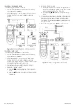
Figure 5:
Example configuration - mA measurement
Operation - Switch test
DPI 812 only. To do tests on an RTD switch:
1. Connect the instrument (Figure 6) and, if necessary,
adjust the
Set Up
2. Select the applicable switch test from
Select Task
(Table 2/3) and, if necessary, adjust the
Settings
(Table 5). The display shows the switch condition (open
or closed) in the top right-hand corner.
3. Supply the output values to the system (Table 7).
• Example - “Nudge” output.
a. Use
Edit
(
■
■
) to set a value less than the switch
value.
b. Use the
▲
▼
buttons to change the value in small
increments.
• Example - “Ramp” output.
a. Set “High” and “Low” values that are applicable to
the switch value (Table 6). Then, to get an accurate
switch value, set a long “Travel” period.
b. Use
Start/Stop
(
■
■
) to start and stop the “Ramp”
cycle.
4. If necessary, supply the output values in the opposite
direction until the switch changes condition again.
The display shows the applicable values to open and
close the switch.
5. To do the test again, press
ESC
to reset the values.
Figure 6:
Example configuration - Switch test
Settings
Settings
a) with external loop
power
b) with internal loop
power
Maximum: 30V
a) Temperature
b) Resistance
Start
Settings
Edit
Settings


