background image

 [EN]  English - 

11

K345 Issue 4

3. To make sure that the calibration is correct, select the 

applicable ohms input task (Table 2).

4. Make a 4 wire connection to the applicable standard 

resistor (Table 10) and measure the value (Figure 1)

5. Make sure that the error is in the specified limits 

(Table 10).

Table 10: 

Ohms input error limits

Calibration - Procedures (Ohms output)

1. Connect the instrument to the calibration equipment 

(Figure 2)

2. Let the equipment get to a stable temperature 

(minimum: 5 minutes since the last power on).

3. Use the calibration menu (Table 9) to do a two-point 

calibration for each range. 

• Range: 0-399.9

Ω

• Range: 400

Ω

-1999.9

Ω

• Range: 2k

Ω

-4k

Ω

The display shows the applicable instructions to
calibrate each range.

4. To make sure that the calibration is correct, select the 

applicable ohms output task (Table 2).

5. Supply the specified values (Table 11). Make sure that 

the error is in the specified limits.

Table 11: 

Ohms output error limits

Calibration - Procedures (mA input)

1. DPI 812 only. Connect the instrument to the calibration 

equipment (Figure 5). 

2. Let the equipment get to a stable temperature 

(minimum: 5 minutes since the last power on).

3. Use the calibration menu (Table 9) to do a three-point 

calibration (-FS, Zero and +FS). The display shows the 
applicable instructions to complete the calibration.

4. To make sure that the calibration is correct, select the 

applicable mA input task (Table 2) and apply these 
values:

• mA: -55, -40, -24, -18, -12, -6, 0 (open circuit)

Then mA: 0, 6, 12, 18, 24, 40, 55.

5. Make sure that the error is in the specified limits

(Table 12)

Table 12: 

mA input error limits 

Calibration - Procedures (IDOS UMM)

Refer to the user manual for the IDOS UMM.
When the calibration is complete, the instrument 
automatically sets a new calibration date in the UMM.

Standard
Resistor*
(

Ω

)

*

Or an equivalent resistance simulator

Resistor


error


(

Ω

)

Permitted 


DPI 811/812 error 


(

Ω

)

0 (Short circuit)

-

0.05

100

0.008

0.05

200

0.013

0.05

300

0.018

0.05

400

0.007

0.05

1k

0.042

0.25

2k

0.052

0.25

4k

0.072

0.50

 Ohms

(

Ω

)

Calibrator


error


(

Ω

)

Permitted 


DPI 811/812 error 


(

Ω

)

0

0.003

0.05

100

0.004

0.06

200

0.005

0.06

300

0.007

0.07

400

0.008

0.07

1000

0.015

0.30

2000

0.026

0.40

4000

0.049

0.80

Applied 
mA

Calibrator


error


(mA)

Permitted 


DPI 811/812 error 


(mA)

±55

0.0022

0.005

±40

0.0018

0.004

±24

0.0014

0.003

±18

0.0004

0.003

±12

0.0003

0.002

±6

0.0002

0.002

0 (open circuit)

-

0.001

Summary of Contents for Druck DPI 811

Page 1: ...Druck DPI 811 812 RTD calibrator and RTD loop calibrator User manual K345 99 Washington Street Melrose MA 02176 Phone 781 665 1400 Toll Free 1 800 517 8431 Visit us at www TestEquipmentDepot com...

Page 2: ...K345 Issue 4 A1 A2 DPI 812 A3 10 1 3 4 2 5 6 7 9 8 A2 A3 11 B1 12 10 14 15 13 20 21 22 25 17 18 26 19 27 16 23 24 B1 Customer service Visit our web site www gesensing com...

Page 3: ...s uses Intelligent Digital Output Sensor IDOS technology to give instant plug and play functionality with a range of Universal Measurement Modules UMM Example the Universal Pressure Module UPM The DPI...

Page 4: ...ion above it on the display Item 25 Example Settings 8 Display Refer to A3 9 SENSOR PC Communications port Use to connect a Universal Measurement Module UMM or a RS232 cable 10 RTD connectors To measu...

Page 5: ...se this instrument together with a HART communicator to set up and calibrate HART devices Scale To select the applicable international temperature scale IPTS 68 or ITS 90 To select and set up the back...

Page 6: ...select and set up a tare value for the measurement task a specified value or the reading on the display The instrument subtracts a positive tare value and adds a negative tare value Additional data S...

Page 7: ...ional Additional data Table 6 Select Settings Step To select and set up values for the Defined Step output Example output cycle Auto Repeat Optional Additional data Table 6 Select Settings Options If...

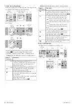
Page 8: ...adjust the Set Up Table 1 2 Select the RTD or Ohms input task from Select Task Table 2 3 and if necessary adjust the Settings Table 4 Figure 1 Example configuration To measure the temperature or resis...

Page 9: ...ransmitter calibration DPI 812 only To calibrate a transmitter 1 Connect the instrument Figure 3 4 and if necessary adjust the Set Up Table 1 2 Select the applicable calibration task from Select Task...

Page 10: ...the top right hand corner 3 Supply the output values to the system Table 7 Example Nudge output a Use Edit to set a value less than the switch value b Use the buttons to change the value in small incr...

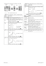
Page 11: ...Settings Table 4 5 2 If necessary do a zero correction Table 4 To measure pressure with another operation Figure 8 use the same procedure Figure 8 Example configuration To measure pressure and temper...

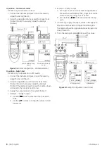
Page 12: ...set the new calibration date for the instrument Calibration Procedures Ohms input 1 Let the equipment get to a stable temperature minimum 5 minutes since the last power on 2 Use the calibration menu...

Page 13: ...nt get to a stable temperature minimum 5 minutes since the last power on 3 Use the calibration menu Table 9 to do a three point calibration FS Zero and FS The display shows the applicable instructions...

Page 14: ...850 0 90 0 50 Pt100 385 IEC 751 328 1562 200 850 0 45 0 25 Pt200 385 IEC 751 328 1562 200 850 1 08 0 60 Pt500 385 IEC 751 328 1562 200 850 0 72 0 40 Pt1000 385 IEC 751 328 752 200 400 0 36 0 20 D 100...

Reviews: