background image


GOM-802 

User 

Manual 

50


PT-100 sensor are listed below: 


Type 


Standard 


Alpha 


Beta 


Delta 


@ 0

˚

PT-100 ITS90  0.003850 0.10863  1.49990  100


Temperature 
Calculation Example 

Example—Calculating the resistance of  a PT-100 
RTD at 100

˚

C (T). The following R

0

 (

at 0

˚

C), 

alpha, beta, and delta values are used for the   
PT-100 RTD: 
 

T=100

˚


R

0

 (


at 0

˚

C) = 100


 Alpha=0.003850 

 Beta=0.10863 

 Delta=1.49990 

A, B, and C are calculated according to equations 
listed above: 
 

A=0.00391 

 B=5.77e-7 

 C=4.18e-12 

The resistance of  the RTD at 100

˚

C (R

100

) is then 

calculated as follows: 

R

100

: =R

0

[1+AT=BT

2

+CT

3

(T-100)] 

 =100{1+[(0.00391)(100)]+[(-5.77e-7)(100

2

)

 +[(-4.18E-12)(100

3

)(100-100)]]} 

 =138.5


Summary of Contents for gom-802

Page 1: ...m Meter GOM 802 USER MANUAL GW INSTEK PART NO 82OM 80200MD1 ISO 9001 CERTIFIED MANUFACTURER 99 Washington Street Melrose MA 02176 Phone 781 665 1400 Toll Free 1 800 517 8431 Visit us at www TestEquipm...

Page 2: ...language without prior written consent of the Good Will company The information in this manual was correct at the time of printing However Good Will continues to improve products and reserves the righ...

Page 3: ...Rear Panel Overview 16 Set Up 17 MEASUREMENT 21 Measurement Overview 22 Resistance Measurement 23 Compare Function 26 Temperature Measurement 32 Temperature Compensation 34 HANDLER SCAN INTERFACE 36 H...

Page 4: ...y appear in this manual or on the GOM 802 WARNING Warning Identifies conditions or practices that could result in injury or loss of life CAUTION Caution Identifies conditions or practices that could r...

Page 5: ...tion Measurement category II is for measurement performed on the circuits directly connected to the low voltage installation Measurement category I is for measurements performed on circuits not direct...

Page 6: ...surface resistivity Pollution degree 1 No pollution or only dry non conductive pollution occurs The pollution has no influence Pollution degree 2 Normally only non conductive pollution occurs Occasio...

Page 7: ...cted to the terminal which is marked with the letter N or coloured Blue or Black The wire which is coloured Brown must be connected to the terminal marked with the letter L or P or coloured Brown or R...

Page 8: ...Please note the information in this manual was correct at the time of printing However as GW Instek continues to improve its products changes can occur at any time without notice Please see the GW Ins...

Page 9: ...r the status of the pass fail testing The relative feature enables the GOM 802 to easily compensate for any stray resistance Up to 20 different sets of HI LO GO settings can be stored to satisfy a num...

Page 10: ...automatic testing The GOM 802 has a handler interface designed for automatic testing The handler interface outputs the status of PASS FAIL HI LO READY and EOT signals and inputs a trigger control sign...

Page 11: ...L Actual and value measurements Manual or Auto ranging Continuous or Triggered measurement modes Temperature compensation and measurement Four wire measurement method Auto recall last setting on power...

Page 12: ...page 18 Primary Value Display Shows the primary measurement results Normal Display Shows the Normal nominal value setting Comparator Indicators The comparator indicators indicate the status of compari...

Page 13: ...Function Keys The COMPTEMP key activates the comparator function The secondary function turns on the temperature compensation function Temperature compensation The Cursor keys are used to edit paramet...

Page 14: ...he milliohm meter between local and remote mode The secondary function will set the I O interface to GPIB or RS 232 GPIB RS232 mode Sets the High limit values The secondary function activates the Hand...

Page 15: ...rnal Turns the internal trigger ON OFF Enter key The SHIFT key is used to access the secondary functions Lower Limit Display LO Displays the lower limit as as a percentage Upper Limit Display HI Displ...

Page 16: ...A 250V For the fuse replacement details see page 47 RS 232C port Accepts an RS 232C cable for remote control DB 9 male connector For remote control details see page 43 GPIB port Accepts a GPIB cable f...

Page 17: ...GETTING STARTED 17 Set Up Tilt Stand Steps 1 Pull handle base away from the casing 2 Turn handle into any of the preset positions Stand Position Carry Position...

Page 18: ...230 100 220 120 230 100 220 120 230 Steps 2 Connect the power cord to the AC Voltage input 220 1 0 0 120 230 CAUTION Ensure the ground connector of the power cord is connected to a safety ground This...

Page 19: ...The Source HI carries the measuring current source It is connected to the side of the DUT Source LO The Source LO terminal accepts the signal return current Connects to the side of the DUT Sense HI M...

Page 20: ...relative value is a negative a minus sign is shown on the MSB most significant bit At low measurement speeds the minus sign will alternate with the displayed measurement 1 Short the cables Short the...

Page 21: ...Using the Trigger Function 25 Compare Compare Function 26 Save Compare Settings 28 Recall Compare Settings 29 Buzzer Buzzer Function 30 Percentage Display as Percentage 31 Relative Relative Function...

Page 22: ...Temperature sensor function AUTO MANSPEED Auto range Manual range SHIFT AUTO MANSPEED Measurement speed function REL VALUE Relative function selector SHIFT REL VALUE Toggle Relative or Value HIGHHANDL...

Page 23: ...ance temperature and temperature compensation mode Press ENTER to confirm 2 Resistance mode display appears Auto Indicates automatic ranging m Milliohms Ohms k Kilo ohms 3 Connect the test lead and me...

Page 24: ...erature compensation function Auto Range Press the Up and Down arrow keys to manually select the resistance range Manual Press the AUTO MAN key to use automatic ranging Selection List Range Resolution...

Page 25: ...h between the LO and HI rates LO rate The low rate is shown with a full scale of 5 digits in the resistance measurement mode HI rate The high rate is shown with a full scale of 4 digits Note For detai...

Page 26: ...NT to return the triggering mode back to internal mode The EXT indicator will become cleared from the display Compare Function Background The compare function compares a measured value to a Normal val...

Page 27: ...setting Use the Left and Right arrow keys to select a digit The selected digit will flash Use the Up and Down arrow keys to edit the value of the selected digit Range 33000 00000 Press ENTER to confir...

Page 28: ...wn arrow keys to edit the value of the selected digit Range 000 999 Press ENTER to confirm the setting Save Compare Settings Background The save function saves the Normal High and Low limit settings i...

Page 29: ...function Note Pressing SHIFT before pressing ENTER will exit the Save mode Recall Compare Settings Background The Recall function retrieves the Normal High and Low limit settings from one of 20 memor...

Page 30: ...unction Note Pressing SHIFT before pressing ENTER will exit the Recall mode Buzzer Function Background The buzzer function can make the buzzer sound when the compare test has passed GO or failed NOGO...

Page 31: ...ue rather than the actual value For example if the Normal value is 20 000 and the actual value is 10 000 then as a percentage it would be displayed as 50 00 1 Select Buzzer Function Press the SHIFT ke...

Page 32: ...the displayed measurement 1 Set the Reference value Press the REL VALUE key 2 Relative mode display appears REL Indicates the Relative function is active Note The Auto range function will be disabled...

Page 33: ...on the NORMAL display 3 Temperature mode connection The temperature sensor uses the rear panel TC port for input Relative Function Background The Relative function can also be used with the temperatur...

Page 34: ...rature compensation mode Press SHIFT COMPTEMP to access the main function mode Press the Up and Down arrow keys to select the TC measurement mode shown above There are three different modes resistance...

Page 35: ...mpensation function Auto Range Press the Up and Down arrow keys to manually select the resistance range Manual Press the AUTO MAN key to use automatic ranging Relative Function Background The Relative...

Page 36: ...HANDLER SCAN INTERFACE Handler Handler Overview 37 Scan Scan Overview 38 Scan Setup 38 Scan Output 41 Interface Configure Interface 42 Configure GPIB Interface 42 Configure RS 232 Interface 43 Interf...

Page 37: ...male Pin Assignment START Start the trigger for a single measurement Negative edge trigger READY High when the measurement has finished The instrument is ready for the next trigger EOT High when the A...

Page 38: ...ls the relay output Pass Pass signal Indicates a GO compare result is GO pass Low Low signal Indicates a LO compare result High High signal Indicates a HI compare result Clock The clock signal will pu...

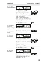
Page 39: ...ENTER to confirm 3 Resistance mode and Compare display appears 4 Resistance Range Press the Up and Down arrow keys to manually select the resistance range 5 Select the Scan mode Press SHIFT NORMALSCAN...

Page 40: ...t the scan Press the MANUAL TRIGINT key to start the sweep measurements The results will be displayed on screen and output through the scan port until finished 9 View Results Press the Up and Down arr...

Page 41: ...nder different conditions are shown below Ready message displayed After the MANUAL TRIGINT key is pressed Relay Pass Low High Clock STRB 1 2 99 100 Scan channel 1 Delay time has elapsed Scan channel n...

Page 42: ...24 pin female GPIB port RS 232 DB 9 male port Configure GPIB Interface Background The GPIB interface is SCPI 1994 IEEE488 1 and IEEE488 2 compliant 1 Select the GPIB address Press SHIFT LOCALGPIB RS23...

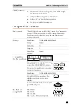
Page 43: ...baud rate parity data bits stop bit and data control settings are used Settings Baud rate 1200 2400 4800 9600 Parity None Data bits 8 Stop bit 1 Data flow control None 1 Select the RS 232 baud rate P...

Page 44: ...ed Interface Function Check Operation Run this query from the terminal idn This should return the Manufacturer Model number and Firmware version GW Inc GOM 802 FW1 00 Function Check Errors If you do n...

Page 45: ...000 counts the measurement speed is 7 readings s at 3 000 counts the measurement speed is 30 readings s The GOM 802 performance does not match the specifications Make sure the device is powered on for...

Page 46: ...re Measurement Reference Temperature Table 48 RTD SensorsTemperature 49 Optional Platinum Sensor 49 Specifications Resistance Measurement 51 Temperature Measurement 52 Temperature Correction Function...

Page 47: ...Fuse Replacement Replace the AC source fuse Steps 1 Remove the power cord 220 1 0 0 120 230 2 Remove the fuse socket using a flat screwdriver 220 1 0 0 120 230 3 Replace the fuse in the holder 220 1...

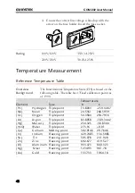
Page 48: ...calibration points as of 1990 Element Type Temperature K C H2 Hydrogen Triple point 13 8033 259 3467 Ne Neon Triple point 24 5561 248 5939 O2 Oxygen Triple point 54 3584 218 7916 Ar Argon Triple poin...

Page 49: ...atinum Sensor Introduction The optional platinum sensor is a PT 100 sensor The PT 100 sensor meets the German DIN43760 1968 3 wire measurement specification These sensors are one of the most common te...

Page 50: ...0 RTD at 100 C T The following R0 at 0 C alpha beta and delta values are used for the PT 100 RTD T 100 C R0 at 0 C 100 Alpha 0 003850 Beta 0 10863 Delta 1 49990 A B and C are calculated according to e...

Page 51: ...100mA 0 05 3 1 772V 30 1m 10mA 0 05 2 1 772V 300 10m 1mA 0 05 2 1 772V 3k 100m 100 A 0 05 2 1 770V 30k 1 100 A 0 05 2 4 570V 300k 10 10 A 0 05 2 4 526V 3M 100 1 A 0 05 2 4 148V 3000 counts Accuracy s...

Page 52: ...3 1 0 C 0 3 3 C Temperature Correction Function Temperature correction range 0 0 C 39 9 C Reference temperature range 0 C 99 9 C Thermal coefficient range 9999 ppm Temperature range Accuracy of temper...

Page 53: ...compare mode is enabled RS 232 GPIB option IEEE488 1 1987 IEEE488 2 1992 and SCPI 1994 The Scan and Handler interface use the same connector Environmental Operation Environment Indoor use altitude up...

Page 54: ...agnetic Compatibility and Low Voltage Equipment Directive the following standards were applied EMC EN 61326 Electrical equipment for measurement control and laboratory use EMC requirements 1997 A1 199...

Page 55: ...supply safety instructions 5 Power up 18 PT 100 sensor temperature calculation 49 Rate setting 25 Rear panel overview 16 Reference temperature table 48 50 Relative function setting 32 33 Resistance s...

Reviews: