- 19 -
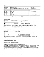
DIODE:
Set the selector switch to measurement range ‘
Ω
’.
Insert the black test lead into the ‘COM’ socket and the red test lead into the right-
hand socket.
Use the ‘M’ button to set the device to
. Using the test probes, touch the test
points of the test object. Red test lead = anode
Black test lead = cathode.
The forward voltage drop is displayed.
CONTINUITY TEST:
Set the selector switch to measurement range ‘
Ω
’.
Insert the black test lead into the ‘COM’ socket and the red test lead into the right-
hand socket.
Using the button ‘M’, set the device to ‘ )) ’. Using the test probes, touch the test
points of the test circuit. An acoustic signal is emitted if resistance below 50
Ω
is
measured. Read measurement value on the display.
Important: Isolate from the power supply and discharge capacitors in the circuit to
be measured.
5. Changing the battery/fuse
Change the battery when the battery symbol is displayed. Remove the test leads
from the measuring instrument before changing the battery or fuse!
Use the specified batteries/fuses only!
Rear of instrument:
Remove the screw on the rear of the instrument, open the battery compartment
and remove the used batteries.
Important: Do not dispose of batteries in normal household rubbish!
Observe statutory regulations pertaining to disposal!
Insert new batteries (2 x 1.5 V AAA Micro). Replace battery compartment cover
and screw tight.
When changing the fuse, always remove the test leads from the instrument and
undo all screws on the rear; carefully remove the rear of the housing and replace
the fuses with fuses of the same type. Fuse: F 200 mA or 4 A/400 V

