background image

Operation manual Pneumator  

   Testo Industrial Services  

   Version 1.4  

   2019  

   Page 9 


Operation / application: 

After selecting the operation mode CTRL and leaving the menu (MENU button) a 
zero adjustment is automatically conducted, in case AUTO ZERO = ON. 
Subsequently, the reference sensor is venting („VENT “).  
 
 
The respective pressure set point value now results now from the nominal pressure 
value (see upper display middle, initial value = full measuring range), multiplied by a 
percentage value (see lower display middle, initial value = 0%). The respective set 
point value is indicated in the lower right display, the unit in the upper right. Note: The 
new set point value is activated immediately after the change of the absolute value or 
of the percental value.  
 

Example

 (compare illustration): 

-  Nominal value: 100.00 Pa 
-  Percental value: 0% 
-  Current set point value =  100 Pa * 0% = 0 Pa 

 
You can switch between the absolute value and the 
percental value by pressing OK.  
 

Change of the percental value (lower display middle - framed bold): 

For the gradual up - and down regulation of the pressure value, e.g. 0 / 25 / 50 / 75 / 
100 % of the absolute value. The step size x is defined in the submenu  „range“ . 
UP:    

Pressure rise of x % of the measuring range  

DOWN: 

Pressure reduction of x % of the measuring range  

0%:   

Pressure = 0 Pa 

100%:  

Pressure = 100% of the measuring range 


Change of the absolute value (upper display center - framed bold): 

For the start-up of a given pressure value, e.g. 610 hPa. In most cases it is advisable 
to leave this value on 100% of the measuring range. 
UP:    

Digit +1 

DOWN: Digit 

-1 

0%:   

one digit position to the left 

100%:  

one digit position to the right 


Retrieval of the calibration data: 

As soon as the central display figure indicates a stable value, the respective 
calibration data can be retrieved:  
- physical unit: Display value upper right 
- pressure set value: Display value in the lower right 
- actual value of test device: Display  of the test device 
- Reference value: Display middle 
 

Manual  zero balance (ZERO) 

In case the reference measuring cell is to be set to zero during the calibration, please 
use the ZERO button. After approximately 3-5 seconds, the previous status is started 
up again. 


Summary of Contents for 0519.0816

Page 1: ...Operation manual Pneumator Testo Industrial Services Version 1 4 2019 Page 1...

Page 2: ...Operation manual Pneumator Testo Industrial Services Version 1 4 2019 Page 2 Order number Measuring range 0519 0816 1 hPa 0519 0817 10 hPa 0519 0818 100 hPa 0519 0819 1000 hPa...

Page 3: ...4 General operation 6 5 Menu setting for all operating modes 7 6 Operating mode CTRL calibration step by step 8 7 Operating mode AUTO calibration programmed steps 11 8 Operating mode MESS Pressure mea...

Page 4: ...ttention The Pneumator is supplied via a power supply with 20 to 26 VDC at an amperage of 1 A Never touch parts under Voltage The inserted reference sensor has an overload protection However please no...

Page 5: ...h relative pressure please attach only to this connector Pressure With differential pressure the lower pressure must be attached here Display Depending upon selected mode of operation all relevant inf...

Page 6: ...programmed at first in the menu and or in its submenus before it is used Programming is done as follows o Usually by operating buttons in this description always written in capital letters Their funct...

Page 7: ...irming with OK o Submenu settings At OK a further menu overview is being opened o Submenu zero At zeroing the reference pressure sensor is being pressurized with the differential pressure 0 Pa by open...

Page 8: ...de press UP or DOWN until CTRL appears Selecting with OK o Submenu Range Define maximal calibration pressure buttons UP DOWN 0 100 confirming with OK Possible value ranges compare chart Pneumator type...

Page 9: ...er display middle framed bold For the gradual up and down regulation of the pressure value e g 0 25 50 75 100 of the absolute value The step size x is defined in the submenu range UP Pressure rise of...

Page 10: ...e pressure value sinks Pressing the LEAK button again you return to the CTRL operating mode Example see display photo Lower left time since pressing LEAK in s here 89 s Lower middle Pressure change in...

Page 11: ...lative pressure test device Connection to Plus Programming o Press MENU o Submenu Mode press UP or DOWN until AUTO is indicated Selecting with OK o Note The sub menus range unit steps in the main menu...

Page 12: ...bmenu T Start Initial waiting time for the venting buttons UP DOWN 0 100 confirm withOK compare illustration and chart Submenu T Stop Waiting time at maximum pressure buttons UP DOWN 0 100 confirm wit...

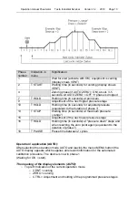
Page 13: ...hase 7 13 T STOP Waiting time in seconds at maximum pressure range 15 Adjustment of the next lower pressure stage 16 T HOLD Holding time in seconds at pressure down steps and when reaching the zero po...

Page 14: ...st of ten cycles power supply operation lower left Retrieval of calibration data The programmed calibration cycles will be started by the OK button As soon as the display middle indicates a stable val...

Page 15: ...S display o Submenu Setting Zero Definition of automatic zero procedure o Auto zero ON right after leaving the menu and then on a regular basis the zero points gets adjusted o Interval Time Distance i...

Page 16: ...the measurement range of the Pneumator If this happens slowly the internal magnetic valve will lock at this value and ERR appears in the display Make sure that the high pressure is no longer present a...

Page 17: ...velocity unit button UP and DOWN confirm with OK The maximum measurement range is indicated in the VELO display upper middle is automatically converted o Submenu Settings Here the submenu VELO FLOW i...

Page 18: ...plug symbol Example compare illustration Operating mode velocity VELO Maximum velocity 40 825 m s Current measurement value 0 m s Density 1 2 kg m3 mains operation bottom left Protection against overl...

Page 19: ...Operation manual Pneumator Testo Industrial Services Version 1 4 2019 Page 19...

Page 20: ...unit button UP and DOWN confirm with OK The maximum measurement range is indicated in the FLOW display upper middle is automatically converted o Submenu settings Here the submenu VELO FLOW is relevan...

Page 21: ...t Rechargeable battery charger display at mains operation plug symbol Example compare illustration Operating mode volume flow FLOW Maximal volume flow 40828 l s Current measurement value 0 m s Tightne...

Page 22: ...ing chart Parameter Possible values Active no use of interfaces USB RS232 BAUD 1200 2400 4800 9600 14400 19200 28800 38400 56000 57600 only selectable if active USB or RS232 Data Bits 8 not changeable...

Page 23: ...en atp 1 10000 CR Pause time phase 18 1 10000 time in seconds atr 1 10000 CR Tolerance band 1 10000 tolerance as factor 0 01 of the measurement range of the equipment As soon as the pressure value fin...

Page 24: ...enu settings saz 0 1 Set auto zero in measuring and control mode 0 off 1 on sbr 0 1 Set baud rate RS232 0 1200 1 2400 2 4800 3 9600 4 14400 5 19200 6 28800 7 38400 8 56000 9 57600 sbu 0 1 Set baud rat...

Page 25: ...3 Trouble shooting Interferance Reason Procedure Device does not function no supply voltage Check whether the plug is connected display is dark right in the IEC socket Switch on the device with the ma...

Page 26: ...mator Testo Industrial Services Version 1 4 2019 Page 26 14 Service Testo Industrial Services GmbH Gewerbestr 3 D 79199 Kirchzarten GERMANY Tel 49 0 7653 681 8000 Fax 49 0 7653 681 8010 info testotis...

Page 27: ...Operation manual Pneumator Testo Industrial Services Version 1 4 2019 Page 27...

Reviews: