5 Installation
28
5.6.1.1 1 x switch output, 1 x analog output
(condition at delivery)
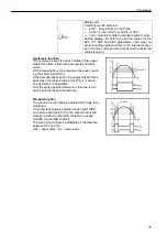
The OUT1 output is used as a PNP signal output (switch signal) and the
OUT2 output is used as an analog output. This is the configuration in which
the electronic sensor assembly is delivered.
5.6.1.2
2 x switch outputs or pulse output
Both of the available OUT1 and OUT2 outputs are each used as a PNP sig-
nal output (switch signal or alternative OUT2 for pulse sequence).
5.6.2
5-wire pin assignment (accessory)
If you use connecting cable available as an option for the electrical isolation
(
See section 3.3.2), the following line assignment is valid for the connect-
ing cable.
Wire colour
Assignment
Brown
+L (19 - 30 V DC) voltage supply
Pink
+ potential-free pulse output (collector) OUT1
White
- potential-free pulse output (emitter) OUT1
Green OUT2
Black
0 V DC (GND)
The potential-free pulse output OUT1 is specified for this connecting cable
as follows:
Line type
LiYCY
Length 5
m
Switching capacity
500 mA
Max. switching voltage
36 V
Min. switching voltage
5 V
Switch contact resistance
0.21 Ohm
Insulation voltage
5.3 kV
Protected against polarity re-
versal
Yes
Pin = designation (wire colour)
1= BN (brown)
2= WH (white)
3 = BU (blue)
4 = BK (black)
Summary of Contents for 0699 6446 Series
Page 2: ...2...
Page 7: ...1 Introduction 7 0699 6446 Standard 1 1 10 1 20 1 30 1 40 3 3 10 3 20 1 50 1 12 1 12 1 11...
Page 41: ...Notes 41...
Page 42: ...Notes 42...
Page 43: ...Notes 43...

