4 Transmitter
35
2.
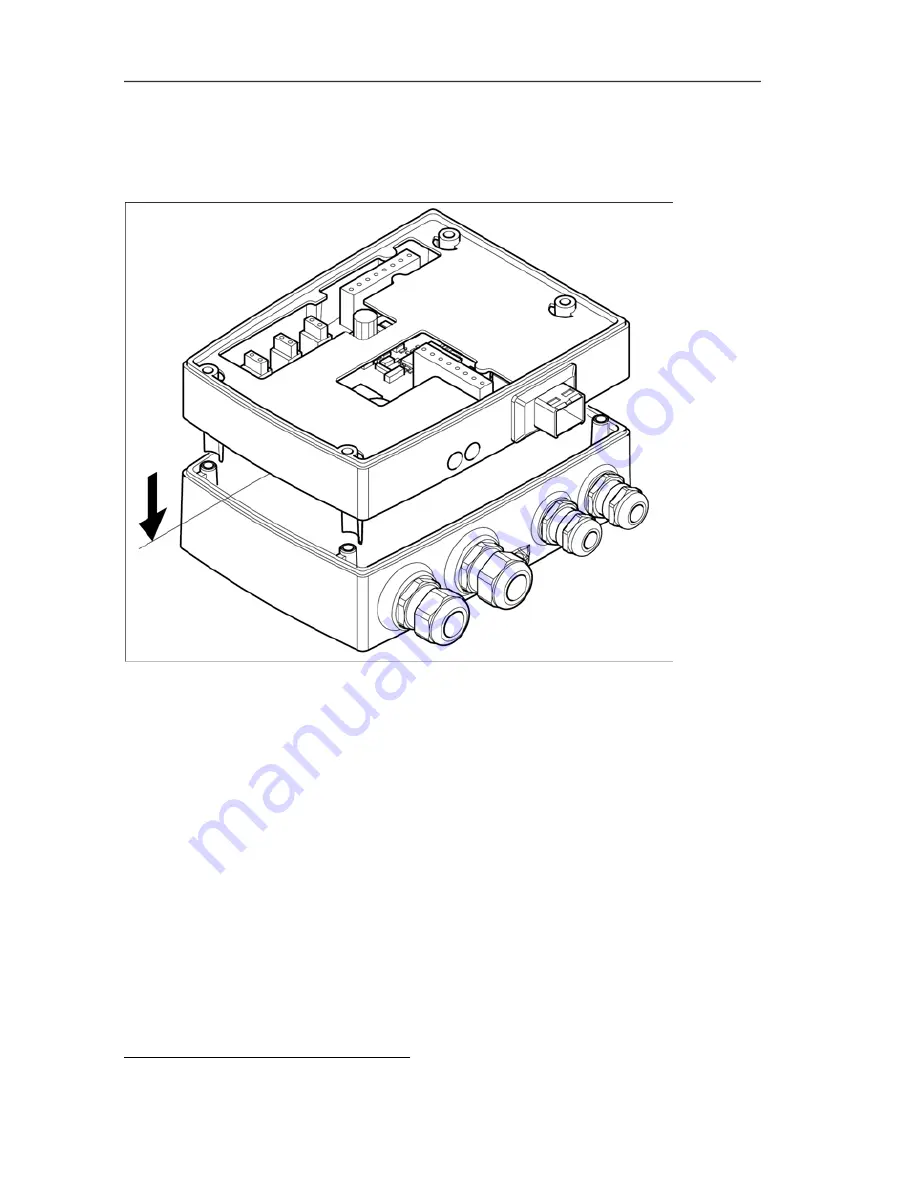
Set DIP switch no. 1 (
1
) at Ethernet module. In the picture: DIP
switch no. 1 off, DIP switch no. 2 on
5
3.
Set Ethernet module on lower part of housing (see arrow).
4.
For the configuration of the Ethernet module, see following
chapter.
5.
If you do not wish to perform a configuration, close the
transmitter.
5
DIP switch no. 2 non-functional
1.800.561.8187
info@Testo-Direct.ca
www.
Testo-Direct
.ca
All manuals and user guides at all-guides.com


