6 testo NanoMet Operation
20
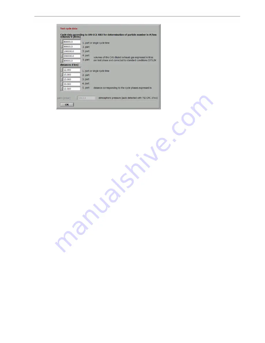
Fig. 6.4 : cycle data information window
6.2.2.
General Measurement Settings
On the 'Config Measurement' tab it is also set if data logging will be started by a trigger signal or
manually and stopped manually or after a predetermined cycle time. Furthermore the sample rate
can be set between 2 and 5
Hz, and the signal averaging interval is set. This setting will have a
significant influence on the amount of data generated during the measurements.
By marking the 'include date in timestamp' control the date will also be saved in the first column
of each entry in the data storage file. This option is usually used for long time and overnight
measurements.
In the bottom line of the 'Config Measurement' tab the path can be set where the logged data
should be saved. This can either be locally on the internal memory of the embedded computer,
an added USB storage device, or an accessible folder in the network where the testo CU-2 digital
control unit is implemented.
The default folder for the logged data to be saved by the testo NanoMet software is
'D:\MEASUREMENT DATA' on the internal flash memory of the embedded computer. The
standard user 'CU-2' has no rights to access other folders.
6.3.
System Configuration
The system components must be specified in the 'Config System' tab shown in Fig. 6.5. The
round check buttons can be activated independently of each other.
6.3.1.
Measurement Instruments
With the round check button, it is set if any testo NanoMet controllable particle detection sensor is
attached and should be used for the measurements, or if just the dilution and conditioning
components testo MD19 -3E Rotating Disk Diluter and testo ASET15-1 Air Supply
/
Evaporation
Tube are controlled by the testo NanoMet software.
The port where the sensor is attached to the testo CU-2 digital control unit can be set.
Selectable sensors are TSI condensation particle counters CPC 3010, 37xx, engine exhaust
condensation particle counter EECPC 3790, GRIMM 5.431 or the EcoChem PAH monitor
PAS2000. The serial number and the measuring unit can be entered.
Furthermore, a CPC correction factor k can be entered, according UN-ECE R83 regulations. This
factor can be used to compensate a certain CPC signal deviation which possibly has been found
when the sensor has been compared to a reference device.


