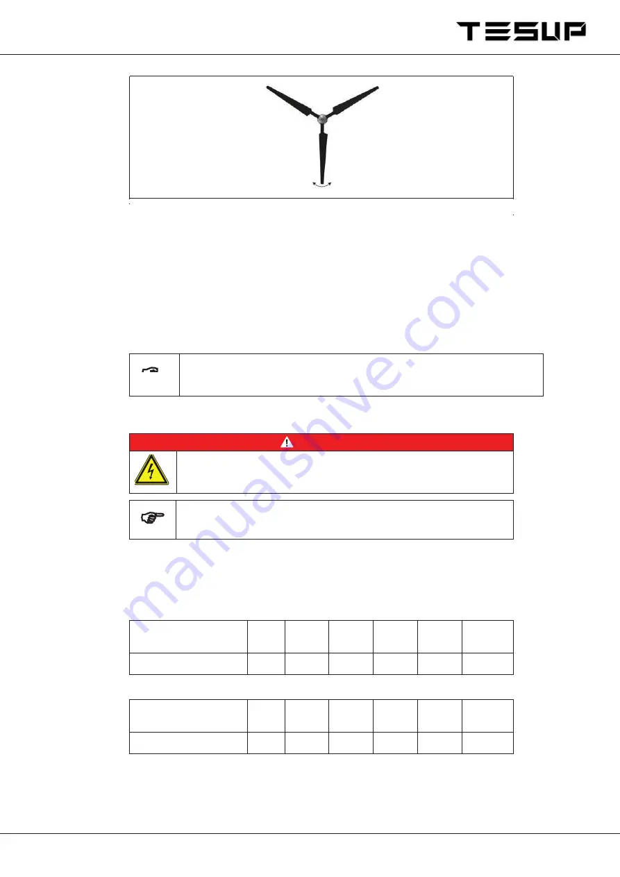
Fig. 7:
Balancing the rotor (Y position)
Danger: High voltage!
All work on electrical equipment must be carried out by a qualified
electrician with the power switched off!
Note: To ensure proper operation, you must use an original
TESUP
charge controller.
Connect a three-wire cable with a suitable cross-section (refer to Table 9 /
Table 10) and the required length to the generator.
Make the electrical connections as shown in Fig. 1:.
Connect the charge controller and the transformer as shown in the
connection diagram (refer to the relevant documentation).
Distance between
generator and charge
controller [m]
< 11 11 – 18 18 – 29 20 – 44 44 – 68 68 – 110
Cable cross-section [mm²]
2.5
4
6
10
16
25
Distance between
generator and charge
controller [m]
< 11 11 – 18 18 – 29 20 – 44 44 – 70 68 – 113
Cable cross-section [mm²]
2.5
4
6
10
16
25
Move rotor to Y position (see Fig. 7)
Carefully release rotor blade.
Observe in which direction the rotor turns (the heavier rotor blade pushes downwards).
Repeat the process for all three positions to determine which rotor blade is in imbalance.
Check repeller for balance
Tighten all screws to 25 Nm.
Check balance again.
Secure all screws with locking varnish.
Note: The repellers have already been tested for equal weight
by the manufacturer.
7
.5
Electrical connections
DANGER!
Table 9 Cable cross-section with
24
V generator voltage
Table 10Cable cross-section with
48
V generator voltage
13
Summary of Contents for i-1500
Page 1: ... Keep handy at the place of use Wind turbine system i 1500 i 2000 USER MANUAL ...
Page 21: ...Fig 9 Declaration of conformity 13 Declaration of conformity 20 ...
Page 23: ...15 Notes 22 ...
Page 24: ...23 ...
Page 25: ...24 ...


