background image

ZEUS 3.0 (MADE IN EUROPE) 

~ 5 ~ 

TESUP 


Before you begin installing, read 

this entire owner’s manual. Identify and note your model 

wind  turbine  where  it  appears  in  this  manual.  Following  the  instruction  and 
recommendations  in  this  manual  will  help  assure  safe  and  enjoyable  use  of  your  new 
renewable energy system. 


Please take the time to read through this manual prior to assembly. 

o


Place this instruction manual in a safe place for reference.  

o


Wait  until  a  calm  day  to  install  or  perform  maintenance  on  your  Turbine  with 
activation of brake. 

o


Listen  to  your  Turbine,  if  you  hear  any  mechanical  noise,  maintenance  may  be 
required, please contact your Turbine dealer. 

o


After installation re-adjust and tighten the screws and bolts. 

o


Adhere to proper grounding techniques as established by the National Electrical 
Code. 

o


Your Wind Turbine must be installed in accordance with this manual and local and 
national building code. Incorrect installation may void your warranty. 

o


Wind Turbine blades spin at a potentially dangerous speed, this must be respected. 
Never approach a Turbine in motion.  

o


Note  wire  size  prior  to  wiring.  Any  under  sizing  of  wire  can  be  potentially 
dangerous. 

o


Check the manual brake periodically. 

o


Check  the  battery  health  periodically.  The  low  battery  voltage  and  improper 
connection can cause over-spin issues. 

2.1.1 Operating and Installing Conditions: 


Please make sure that: 

o


The wind turbine system has been erected correctly by a suitably trained 
person. 

o


All operating personnel have read and fully understood this translation of the 
original instructions 

o


The wind turbine system is properly maintained and repaired. 


2.


GENERAL 

2.1 GENERAL INSTRUCTIONS: 


Summary of Contents for ZEUS3.0

Page 1: ...ZEUS3 0 MADE IN EUROPE TESUP ZEUS3 0 Wind Turbine USER MANUAL Made in Europe POWER IS IN CREATING Revision Index 00 Revision Date ENGLISH EN ...

Page 2: ...ZEUS 3 0 MADE IN EUROPE 2 TESUP A GLIMPSE OF ZEUS 3 0 ...

Page 3: ...General Arrangement Drawing 13 5 Controller 14 5 1 Technical Details 14 5 2 Wiring Diagram 15 5 3 Permissible Storage Operation 16 6 Safety Information 17 6 1 Modifications or changes by the user 17 6 2 Residual Risks 17 6 3 Personnel Requirements 17 6 4 Important Safety Instructions 17 7 Pre Use Preparation 18 7 1 Shipping Conditions 18 7 2 Prerequisites at the place of use 18 7 2 1 Permissible w...

Page 4: ...ons during maintenance work 26 10 2 Inspection and maintenance schedule 26 10 3 Maintenance and cleaning by the user 27 11 Troubleshooting and diagnostics 28 12 Removal from service and disposal 29 12 1 Final decommissioning of the wind turbine system 29 12 2 Disposal of the wind turbine system and components 29 13 Declaration of Conformity 30 14 Appendix 31 15 Manufacturer Details Customer Suppor...

Page 5: ...proper grounding techniques as established by the National Electrical Code o Your Wind Turbine must be installed in accordance with this manual and local and national building code Incorrect installation may void your warranty o Wind Turbine blades spin at a potentially dangerous speed this must be respected Never approach a Turbine in motion o Note wire size prior to wiring Any under sizing of wi...

Page 6: ...ke a note DANGER Immediate danger can cause serious injury WARNING Potential Danger can cause Serious injury CAUTION Potential Danger can cause moderate injury NOTE Useful Tips OTHER SIGNS USED GENERAL WARNING HIGH VOLTAGE MAY START WITHOUT WARNING ENVIORNMENTAL HAZARD SAFETY SYMBOLS ...

Page 7: ...horised representative apply 2 4 PRODUCT FEEDBACK Please notify the manufacturer or his authorised representative about any of the following o Accidents o Potential safety hazards associated with the wind turbine system o Ambiguities in this translation of the original instructions o Description of the wind turbine system ...

Page 8: ...iability will be accepted by the manufacturer if the equipment has been altered as well as in the event of improper assembly installation start up operation maintenance or repair Only original parts supplied by the manufacturer are approved as spare parts or accessories Any spare parts or accessories not supplied by the manufacturer have not been tested for operation and could be detrimental to re...

Page 9: ...US 3 0 MADE IN EUROPE 9 TESUP 3 3 SYSTEM COMPONENTS NOTE Several Batteries can be connected in Parallel Or series depending upon the system voltage ZEUS3 0 WIND TURBINE INVERTER BATTERY CHARGE CONTROLLER ...

Page 10: ...SUP 3 4 WIND TURBINE COMPONENTS Item No Description Quantity 1 Nose 1 2 Turbine Blades 3 3 Hub for holding the blades 1 4 Generator 1 5 Boom for wind direction flag 1 6 Tail vane 1 7 Adapter stud 37 mm PART LIST TABLE 6 1 5 3 2 7 4 ...

Page 11: ...ION Any TEST STANDARDS EN 61000 6 1 electromagnetic compatibility immunity EN 61000 6 3 electromagnetic compatibility emissions ROTOR BLADES MATERIAL Composites HUB FLANGE Cast Steel DIAMETER 2 25 m WEIGHT PER ROTOR BLADES 720 g DIRECTION OF ROTATION From the front in a clockwise direction STARTING WIND SPEED 2 m s NO OF BLADES 3 MAX RPM 1200 MAX SPEED Hurricane scale III NOISE 60 dB PARAMETER 4 P...

Page 12: ...ZEUS 3 0 MADE IN EUROPE 12 TESUP 4 1 1 POWER CURVE POWER CURVE ...

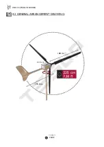
Page 13: ...ZEUS 3 0 MADE IN EUROPE 13 TESUP 4 2 GENERAL ARRANGEMENT DRAWING 31 5 cm 193 0 cm 108 cm ...

Page 14: ... has high efficiency and no load losses The version of the controller will significantly increase the life and sustainability of all the component of the system The special features and product information are listed below o Use of solid state components o Manual brake function o Increasing the life of the controller Microprocessor controlled charge with integrated voltage and current limiting o D...

Page 15: ...trical energy 2 Switch AC Emergency Stop Button Emergency shutdown When pressed the wind turbine must be short circuited 3 Charge controller Generates electrical voltage 24 48 VDC Optionally The TESUP charge controller 4 Battery Stores electrical energy Acid Gel 5 Solar panels Convert solar energy into electrical energy 6 To converter Converts 24 48 VDC into 110 220 VAC ...

Page 16: ...DE IN EUROPE 16 TESUP 5 3 STORAGE OPERATION STORAGE o Ambient temperature 15 to 40 C o Storage location Dry frost free OPERATION o Ambient temperature 25 to 40 C o Place of use Max SWTS Class III acc to EN 61400 2 ...

Page 17: ... persons must be familiar with the safety devices and regulations prior to carrying out the work Authorised persons are defined as follows Operating mode Necessary qualifications Erection Suitably trained persons Normal operation Trained personnel Cleaning Trained personnel Maintenance Suitably trained persons Repair Manufacturer PERSONNEL REQUIREMENT TABLE 6 4 IMPORTANT SAFETY INSTRUCTIONS Proper...

Page 18: ...classes please contact the responsible authorities or your nearest meteorological office The place of use must be free of obstacles alternatively the wind turbine must be erected with a sufficient height refer to Fig 7 PRE USE PREPARATION WARNING Danger to life due to operation in non approved wind classes The wind turbine system may only be operated at Class III wind sites NOTE When choosing the ...

Page 19: ...tails The soil must have a sufficient load bearing capacity The size and structure of the foundation depend on the soil characteristics MOUNTING DETAILS NOTE Ask a qualified structural engineer for advice regarding the optimal design of the foundation ...

Page 20: ...ose 4 to hub with M8x75 screw Screw wind vane 5 to boom with M8x60 bolt Plug in pin 37 mm as mast connection Balancing the rotor Move rotor to Y position see Fig 7 Carefully release rotor blade Observe in which direction the rotor turns the heavier rotor blade pushes downwards Repeat the process for all three positions to determine which rotor blade is in imbalance Check reveller for balance Tight...

Page 21: ...ZEUS 3 0 MADE IN EUROPE 21 TESUP ASSEMBLY PROCEDURE ...

Page 22: ...ocumentation Distance between generator and charge controller m 11 m 18 m 29 m 44 m 68 m 110 m Cross section 2 5 sq mm 4 sq mm 6 sq mm 10 sq mm 16 sq mm 25 sq mm CABLE DETAILS 24V Distance between generator and charge controller m 11 m 18 m 29 m 44 m 70 m 113 m Cross section 2 5 sq mm 4 sq mm 6 sq mm 10 sq mm 16 sq mm 25 sq mm CABLE DETAILS 48V WARNING All work on electrical equipment must be carr...

Page 23: ...ube over each wire of the cable Twist and solder each wire of the cable to the wire from the generator Pull heat shrink tubing over the solder joint and shrink Wrap each wire with textile insulating tape 7 6 ERECTING THE WIND TURBINE Attach the wind turbine to the tower Be careful not to damage the cable Screw wind generator to mast Erect the mast Align the mast vertically in all directions Brace ...

Page 24: ...ontroller The brake is released The fast blinking red LED on the TESUP charge controller goes out The wind turbine system supplies power 8 2 RESTART AFTER EMERGENCY Make sure the risk has been removed Switch on the wind turbine system section 8 1 8 REGULAR OPERATION NOTE For information on operating the charge controller refer to the separate instructions ...

Page 25: ...TEMPORARY SHUTDOWN Switch on the brake The wind turbine is short circuited via the TESUP charge controller This type of shutdown can occur during the stormy weather when the wind speed is higher than 27 m s 9 3 PROLONGED SHUTDOWN Switch on the brake The wind turbine is short circuited via the TESUP charge controller 9 SHUTTING DOWN THE WIND TURBINE ...

Page 26: ... Are the rotor blades balanced Mounting Base Check for vibration Check the guy wires Is the Base mounted properly Inspect for damage Wind turbine Check the bolts Electrical wiring Inspect the cables for damage INSPECTION SCHEDULE TABLE Refer to the supplementary documents for information on maintaining supplier components 10 MAINTENANCE WARNING Risk of injury when carrying out maintenance work X S...

Page 27: ...E USER Coat the wind turbine and the rotor blades regularly with commercially available underbody protection wax using a soft cloth NOTE A wax film protects the surfaces of the wind turbine and the rotor blades from the weather and increases the efficiency of the blades ...

Page 28: ...er not aligned vertically Align the tower vertically Tower bends in the wind Design a more robust tower Tower foundation has too much clearance Reduce the clearance to a minimum Wind turbine system produces too little power Wind turbine or charge controller defective Contact the manufacturer or a specialist dealer Battery defective Replace the battery Battery too small Use a larger battery at leas...

Page 29: ...2 2 DISPOSAL OF THE WIND TURBINE SYSTEM AND COMPONENTS Where necessary dispose of the individual components in consultation with the responsible local authorities Wind turbine system Wiring electrical components Dispose of as electronic scrap Mechanical components Segregate prior to disposal DISPOSAL DETAIL TABLE 12 REMOVAL FROM SERVICE AND DISPOSAL WARNING Risk of injury due to unqualified disman...

Page 30: ...ZEUS 3 0 MADE IN EUROPE 30 TESUP 13 DECLARATION ...

Page 31: ...IST TABLE PAGE 11 PARAMETERS PAGE 12 POWER CURVE PAGE 15 WIRING DIAGRAM PAGE 17 PERSONNEL REQUIREMENT TABLE PAGE 19 MOUNTING DETAILS PAGE 21 ASSEMBLY PROCEDURE PAGE 22 CABLE DETAILS PAGE 26 INSPECTION SCHEDULE TABLE PAGE 27 TROUBLESHOOTING DETAIL PAGE 29 DISPOSAL DETAIL TABLE 14 APPENDIX ...

Page 32: ...ZEUS 3 0 MADE IN EUROPE 32 TESUP TESUP HEADQUATERS 22 SUTTON LANE NORTH CHISWICK LONDON W4 4LD UNITED KINGDOM TESUP OFFICIAL WEB STORE ONLINE CHAT 15 MANUFACTURER DETAILS CUSTOMER SUPPORT ...

Page 33: ...ZEUS 3 0 MADE IN EUROPE 33 TESUP 16 NOTES ...

Reviews:

Related manuals for ZEUS3.0