background image


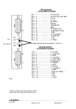
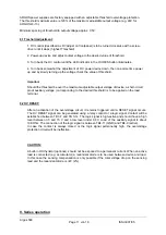
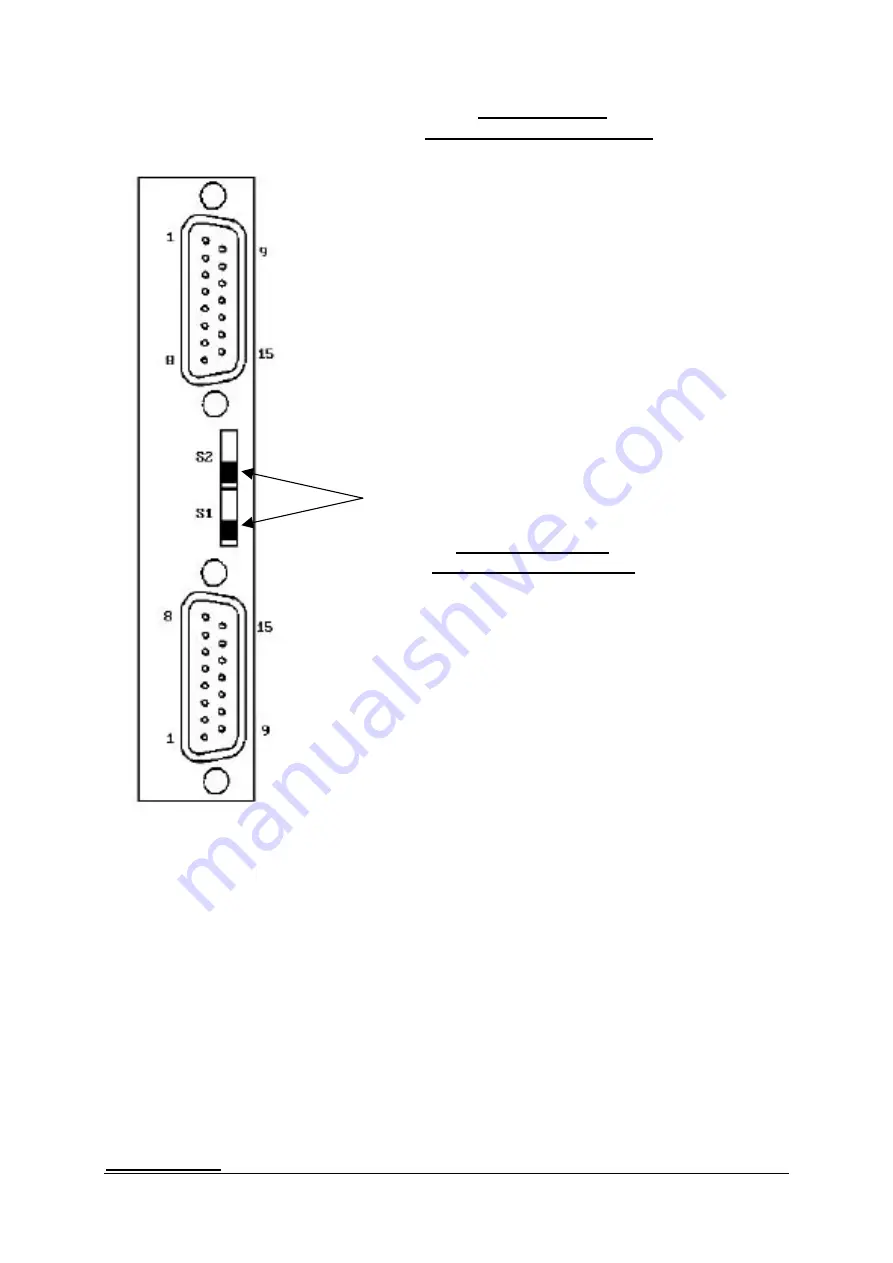
TB 4 pin layout 

     15 Pin Sub-D connector 
 

TB 4 - 1 .............................. CC STATUS 

RCP 

TB 4 - 2 .............................. OV STATUS LATCHED 
TB 4 - 3 .............................. (-) 15V 
TB 4 - 4 .............................. (+) 15V 
TB 4 - 5 .............................. OV PROG 
TB 4 - 6 .............................. I PROG 
TB 4 - 7 .............................. U-MONITOR 
TB 4 - 8 .............................. GND 
TB 4 - 9 .............................. OV RESET DIG 
TB 4 - 10 .............................. REM ON/OFF DIG 
TB 4 - 11 .............................. GND 
TB 4 - 12 .............................. OTP-STATUS 
TB 4 - 13 .............................. I-MONITOR 
TB 4 - 14 .............................. GND 
TB 4 - 15.............................. U PROG 
 
Setting and Function see chapter 7.2 and 7.4 


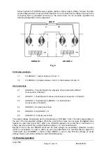
TB 3 PIN LAYOUT 


15 Pin Sub-D connector 


RVP/TRACKIG 

TB3 

TB4 

ON 
 
OFF 
 
ON 
 
OFF


TB 3 - 1............................... (+) SLAVE 
TB 3 - 2............................... (+) MASTER 
TB 3 - 3............................... (+) RCP 
TB 3 - 4............................... (+) 10V REF 
TB 3 - 5............................... (-) TRACKING 
TB 3 - 6............................... REM ON/OFF 
TB 3 - 7............................... OV RESET 
TB 3 - 8............................... (+) RVP 
TB 3 - 9............................... (-) SLAVE 
TB 3 - 10 .............................. (-) MASTER 
TB 3 - 11 .............................. (-) RCP 


TB 3 - 12 .............................. GND or U-PROG * 


TB 3 - 13 .............................. GND 


TB 3 - 14 .............................. GND 


TB 3 - 15 .............................. (-) RVP 

Fig 3 


* After june 1993 (Layout 4200-P1005): U-PROG 
* Before june 1993 (Layout 4200-P0005): GND 


Argos 500 
     Page 

von 

16 

   ISSUE 

07/05 

3. Installation 
Summary of Contents for ARGOS-500

Page 1: ...rieAlpine Allee 1 D 94513 Schönberg Tel 49 0 85 54 9609 0 Fax 49 0 85 54 96 09 20 Mail sales tetelectronics de INSTRUCTION MANUAL ARGOS 500 High performance power supplies Argos 500 Page 1 von 16 ISSUE 07 05 ...

Page 2: ...th current limiting 5 Constant current operation with voltage limiting 6 Sensing compensation 7 External programming 8 Overvoltage protection 9 Serial mode 10 Parallel mode 11 Tracking 12 Monitor and Status outputs 13 Over temperature protection 14 Appendix 15 References to special equipments Argos 500 Page 2 von 16 ISSUE 07 05 ...

Page 3: ... Continuously from 100mA up to rated current adjustable with a 10 turn potentiometer Regulation accuracy LINE 0 01 by 10 line fluctuation LOAD 0 1 from full load to short circuit Temperature coefficient 0 01 K measured in a range of 0 50 C 1 Wichever greater Physical Specifications Physical Specifications Dimensions H x W x D without function elements however with rearpanel connectors 88x443x390 m...

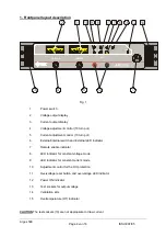
Page 4: ...tment control 10 turn pot 6 External internal switch and External LED indicator 7 Remote enable indicator 8 LED indicator for constant voltage mode 9 LED indicator for constant current mode 10 Adjustment control for the OV protection 11 Overvoltage reset button and overvoltage LED indicator 12 Power ON indicator 13 Test sockets for output voltage 14 Ventilation slits 15 Overtemperature OT indicato...

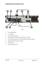
Page 5: ...enbuchse S1 S2 Fig 2 1 Power supply rearpanel 2 Load terminals 3 AC input and main fuse TB1 4 Terminal block for sense line and output voltage V V TB2 5 Opt 34 IEEE bus interface connector address switches and RS 232 connector 6 Regulation board with TB3 TB4 S1 and S2 7 Grounding screw 8 Blind frame for switch S1 S2 Argos 500 Page 5 von 16 ISSUE 07 05 ...

Page 6: ...5 U PROG Setting and Function see chapter 7 2 and 7 4 TB 3 PIN LAYOUT 15 Pin Sub D connector RVP TRACKIG TB3 TB4 ON OFF ON OFF TB 3 1 SLAVE TB 3 2 MASTER TB 3 3 RCP TB 3 4 10V REF TB 3 5 TRACKING TB 3 6 REM ON OFF TB 3 7 OV RESET TB 3 8 RVP TB 3 9 SLAVE TB 3 10 MASTER TB 3 11 RCP TB 3 12 GND or U PROG TB 3 13 GND TB 3 14 GND TB 3 15 RVP Fig 3 After june 1993 Layout 4200 P1005 U PROG Before june 19...

Page 7: ...trol knob CURRENT The lower limit for the constant current operation is 100mA It is important to be careful particularly when working with small output currents since the charging or discharging currents of the output capacitor affects the constant current depending on the charging condition of the output capacitor under dynamic loading condition The output voltage to be maximum limited is adjuste...

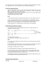
Page 8: ...ity and Tc of ARGOS depends on the auxiliary source specifications 7 2 RVP Resistance Voltage Programming The output voltage can be externally programmed using a 0 to 10 kOhm resistance The configuration is shown here under TB3 8 Rprog 0 10kOhm TB3 14 TB3 15 The output of the power supply is Vout Rprog 10 x Vmax Rprog in kOhm Vout Vmax in volt NOTE a In order to prevent stability fault it is recom...

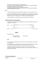
Page 9: ...ong programming leads 3 Ripple stability and Tc of ARGOS depends on the auxiliary source specifications 7 4 RCP Resistance Current Programming The output current can be programmed externally by means of a 0 to 20 KOhm resistance The configuration is as following Rprog 0 20kOhm TB3 3 TB3 11 Shield The output current is Iout Rprog 20 xImax Rprog in kOhm Iout Imax in Ampere NOTE a In order to prevent...

Page 10: ...50µA 7 6 If only one output parameter is to be programmed it is possible to adjust the non programmed parameter to the maximum value In order to achieve this the non programmed input TB4 15 or TB4 6 is connected with the 10V REF output TB3 4 The 10V REF auxiliary voltage may be loaded to max 15mA and is shortcircuit proof 7 7 Remote ON OFF The power supply can be switched on and off using a relay ...

Page 11: ...rresponding to the desired threshold is to be applied on the load terminal 8 2 OV RESET After an activation of the overvoltage circuit it remains triggered until a RESET signal occurs The OV RESET signal can be generated using a relay contact or a logic signal Contact will be established between TB 3 7 and TB 3 14 The logic signal is high active and should have a high level between 3 5 and 15 V an...

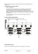
Page 12: ...d terminal cross section 5A mm 2 4 ARGOS 2 S to plus pole of load 2 5 ARGOS 2 S to ARGOS 1 S 2 6 ARGOS 1 S to minus pole of load The output voltages are adjusted via the corresponding VOLTAGE Pots The total output voltage is the sum of the two adjusted voltages When the current limit values are not equal the higher value applies as valid total current limit When one ARGOS surpasses its current lim...

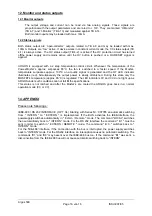
Page 13: ... is not possible to ensure a simultaneously switch off of the devices in case of an over voltage decoupling diodes should be used In that case a sensing compensation is not possible see also point 8 If an accurate regulation in necessary an Auto Load Share Parelling operation is to be configured point 10 2 10 2 Auto Load Share Paralleling Operation only possible with supplies of same voltage and c...

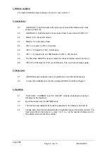
Page 14: ...o on 2 9 TB 4 15 of first slave to TB 3 4 of first slave This one do for all slaves again 3 Please note 3 1 All ARGOS power supplies have to be switched on and off simultaneously 3 2 In view of the stability no more than 3 slave ARGOS should be configured 4 Operation 4 1 VOLTAGE CURRENT and OV ADJUST controls of all slaves are turned clockwise to the maximum 4 2 By all the slaves push the EXTERN k...

Page 15: ...stor R1 should be oversized eg 2W with a Tc of 20ppm C NOTE a In tracking mode the slave ARGOS is to be set in RVP mode S1 right EXTERN not pushed However a programming resistor is not connected consequently RVP programming is set to zero Because the output voltage results from the highest programmed value the tracking mode affects the total output voltage range b The slave output voltage always r...

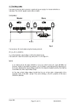
Page 16: ...d Simultaneously the output power is slowly diminished During this state only the MOSFET s temperature approx 85 C is regulated The LED indicators CV and CC do not light up as ARGOS under such conditions can not full fill the specifications This status is not latched and after the Mosfet s are cooled the ARGOS goes back in a normal operation mode CC or CV 14 APPENDIX Please note followings IEEE 48...

Reviews: