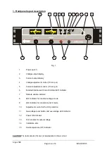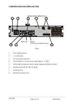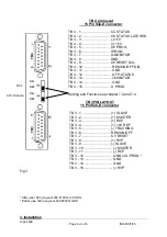
The auxiliary programming voltage is connected as following :
minus to TB 4-14, plus to TB 4-6. When the EXTERNAL switch is pushed and the EXTERNAL
mode active, the yellow LED indicator illuminates.
The programming voltage may have values between 0 and + 10V.
The output current results in a linear and proportional manner from the programming voltage.
Load for the auxiliary source is 150µA.
NOTE
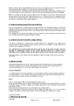
1. When the programming line is interrupted during operation, the output current drops to zero.
2. When using long programming leads it is recommended to use shielded cable in order to
prevent external distortions. It is also recommended to apply accordingly blocking capacitors to
the terminals in case of oscillation due to the inductivity of long programming leads.
3. Ripple, stability and Tc of ARGOS depends on the auxiliary source specifications.
7.4 RCP (Resistance Current Programming)
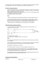
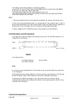
The output current can be programmed externally by means of a 0 to 20 KOhm resistance. The
configuration is as following:
Rprog 0.....20kOhm
TB3-3
TB3-11
Shield
The output current is :
Iout=(Rprog/20)xImax
Rprog in kOhm
Iout, Imax, in Ampere
NOTE
a) In order to prevent stability fault it is recommended to use oversized resistors (eg. 2W) with a
Tc of <=20ppm/¦C.
b) During RCP mode the sliding switch S2 on the rear panel must be positioned on the right side
and the ‘‘EXTERN’’ switch on the frontpanel in the position ‘‘INTERN’’ (not pushed).
c) When Rprog>=20KOhm (interruption), the output current will only be limited to about
1.2xImax by the primary current limiting of the inverter. In this case however the CC LED on the
frontpanel will not illuminate.
7.5 External OV-programming
Argos 500
Page
9
von
16
ISSUE
07/05


