6. Remote sensing
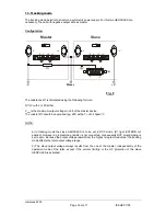
Unavoidable voltage drops across the output terminals and the load lines can be compensated by
including sensing leads in conjunction with the load. However it is important to make sure not to
exceed a voltage drop of 1V or 1% from rated Voltage 1) per load line.
Circuit configuration
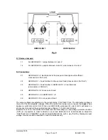
1. Jumpers bV and +S and between -V and -S (terminal TB2 on the rear panel) are opened
2. The load leads (+V,-V) are linked to the output terminals of the supply and the sensing leads to the
sensing terminals and then connected accordingly to the load.
NOTE
The +V, -V terminals at TB2 are not appropriate as power source !
When using the HERCULES power supply with interrupted sensing leads, the specified data can no
longer be fulfilled. However the power supplies are internally protected so that no damage will result
even with opened S-leads.
When using long sensing leads it is recommended to use shielded cables.
When proceeding with interrupted sensing leads the display will show approx. 2V or 2% from rated
Voltage 1) less than the actual output voltage. The current display gives always the true value.
1) whichever greater
7. External programming
The output voltage, current and OV protection can be adjusted externally with programming voltages.
The voltage and current can also be adjusted by means of resistance programming.
NOTE:
Power-supplies with IEEE-488 / RS-232-interface (Opt.34) should be not programmed with external
voltages. If such a programming is unavoidable, please disconnect the interface-card form the power-
supply.
7.1 External voltage programming
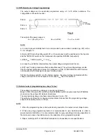
The programming voltage source is connected with its minus lead to TB4-8 and its plus lead to
TB4-15. To activate the external mode the switch ‘‘EXTERN’’ is pushed. The yellow LED
indicatior illuminates if the external mode is active.
The programming voltage may have values between 0 and + 10V. The output voltage is linear
and proportional to the programming voltage.
The load for the auxiliary source is 150µA.
NOTE
1. When the programming line is interrupted during operation, the output voltage drops to zero.
2. When using long programming leads it is recommended to use shielded cable in order to
prevent external distortions. It is also recommended to apply accordingly blocking capacitors to
the terminals in case of oscillation due to the inductivity of long programming leads.
3. Ripple, stability and Tc of Hercules depends on the auxiliary source specifications.
Hercules 5000
Page
8
von
17
ISSUE
07/05

