background image

6

· 

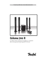
Columa 700 R

Unpacking

Fold  back  the  flaps  on  the  top  of  the  box,  re-
move the polystyrene pieces and carefully lift the 
speaker out of the box. Alternatively you can fold 
back the flaps on the top of the box and turn the 
box and the contents upside down. Then remove 
the box from the contents and remove the inner 
packaging. For your own benefit, we recommend 
that you do not dispose of the box as it can be 
used  to  guarantee  safe  transport  if  the  device 
requires servicing later on. 

Unpacking · Contents

First please check that the 

delivery is complete.

Please note: 

Please keep the boxes for at least 

the eight-week return period, 

as we can ONLY repay the full 

purchase price if the products 

are returned in the ORIGINAL 

PACKAGING in which they were 

supplied!

FM auxiliary aerial

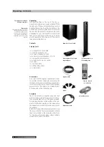
Contents 

Columa 700 R

4

1 x Subwoofer CL 700/6 SWR 

4

1 x centre speaker CL 70 C 

4

4 x column speakers CL 70 FR

4

4 x bases for column speakers CL 70 FR

4

1 x subwoofer remote control

4

2 x batteries for remote control

4

4 x spikes

4

1 x speaker cable

4

1 x FM auxiliary aerial

4

1 x mains cable

Subwoofer CL 700/6 SWR

Remote  control 
+ 2 x batteries

Centre speaker CL 70 C inclu-
ding table base

Column speaker CL 70 
FR including base

Spikes

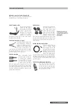
Accessories

As a result of differing user requirements, other 
connection cables or subwoofer casters are not 
included. You can, however, order any required ac-
cessories directly from us. You will find all optional  
accessories for the Columa 700 R Dolby Digital/
DTS subwoofer on the following page.

Assembly

The  CL  700/6  SWR  is  a  downfire  subwoofer  that 
outputs  its  bass  signals  downwards.  It  is  there-
fore  essential  that  you  use  the  spikes  provided. 
To avoid any scratches to the surface or the sub-
woofer itself while screwing on the spikes, place 
the subwoofer on a stable surface and use a cover 
for padding.
Before starting up the system you must also screw 
the bases onto the four column speakers. Attach 
them  as  described  in  the  assembly  instructions 
for the subwoofer spikes, always using a suitable 
screwdriver to attach the bases.

Mains power cable

Speaker cable

Summary of Contents for Columa 700 R

Page 1: ...Technical specifications and operating instructions 5 1 channel home cinema set including 5 1 subwoofer with an integrated Dolby Digital DTS receiver Columa 700 R...

Page 2: ...If one or more components are returned any price discount given by Lautsprecher Teufel on all components in a set as part of the price for the set is waived When returning a component the customer wil...

Page 3: ...Page 11 Remote control Page 12 Operating elements Remote control Page 13 Connection Page 14 Signal sources with digital outputs Page 14 Signal sources with analogue outputs Page 15 Aerial Speakers Pag...

Page 4: ...able could get crushed Dam aged cables must be replaced Pay particular attention to the cable plug connection the mains socket and the cable output from the subwoofer The power supply cable and the ca...

Page 5: ...ges 14 and 15 of these instructions We recommend the Columa 700 R for providing sound in rooms up to 30 m in size Please read these instructions carefully before operating the unit and store the manua...

Page 6: ...subwoofer remote control 42 x batteries for remote control 44 x spikes 41 x speaker cable 41 x FM auxiliary aerial 41 x mains cable Subwoofer CL 700 6 SWR Remote control 2 x batteries Centre speaker C...

Page 7: ...re cleaning These casters can be used instead of the supplied reso nance damper Teufel speaker cable 2 x 2 5mm2 This highly flexible copper wire with transparent sheath and marking to indicate polarit...

Page 8: ...ys use our recommendations to experiment with what works best acoustically and optically Let your ears and eyes decide Setting up the 5 1 configuration Subwoofer You can put the subwoofer anywhere you...

Page 9: ...at you instead angle the speakers more into the room Rear A B Rear SW Centre Front Front Rear A B Rear Front The front speakers are placed at equal distances to the right and left of the TV in old ste...

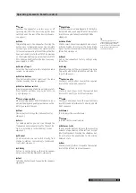
Page 10: ...inputs are selected in sequence each time you press the button Volume This increases the overall volume of the system Volume This decreases the overall volume of the system During operation the displ...

Page 11: ...is switched on U Power connection Connect the power supply cable supplied or the appropriate power supply cable for your region to the subwoofer I Fuse This is the location of the subwoofer fuse The...

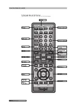
Page 12: ...AX VCR AUX 1 4 7 2 5 8 3 6 9 10 MEM PC STEREO MONO NIGHT MODE LISTEN MODE TEST C DELAY RESET TUNER S DELAY B A S S T R E B L E Balance L R VOLUME VOLUME O Channel I Scan W Mute U Mem Y Stereo mono swi...

Page 13: ...eaker Only works with Dolby Digital dts page 19 Test Initialises the test sound to equalise the speakers page 18 Night Mode Activates reduced volume playback for Dolby Dig ital signals with sound adju...

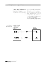
Page 14: ...igital connection cable coaxial Digital connection cable optical Optical out coaxial out The CL 700 6 SWR is perfectly suited for combina tion with a maximum of two of the appliances given above Conne...

Page 15: ...be used with the analogue devices of your choice This requires either a stereo cinch cable Aux VCR or a 3 5 mm stereo mini jack cable PC for each device Connect the players as shown in the illustra t...

Page 16: ...coaxial cable e g a cable connection can be connected directly to the FM coax input instead of the sup plied auxiliary aerial Connecting the satellite speakers The five satellite speakers for the treb...

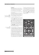
Page 17: ...pt Coax VCR Aux PC Tuner You can set the desired overall volume using the Volume and buttons With the CL 700 6 SWR it is possible to make all settings using the remote control To do this first insert...

Page 18: ...the centre the two rear speakers and the subwoofer to the posi tions r and p on the remote control until the volume of these four speakers corresponds to the volume of the two front speakers Equalisat...

Page 19: ...b applies In small rooms up to 20 m set a delay value of 15 ms and in medium sized rooms 20 30 m set a value of 20 ms Note The setting option of the delay of the rear speaker is only provided in the D...

Page 20: ...TUNER S DELAY B A S S T R E B L E Balance L R VOLUME VOLUME E Playback Digital and analogue signal sources Listen mode Night mode The abbreviation St signifies stereo mode Stereo playback of devices...

Page 21: ...going until it finds the next sta tion Once you have used the Scan I button on the remote control to find the station of your choice press the MEM U button to select the desired memory space e g 1 Th...

Page 22: ...sing an extension lead In ad dition try disconnecting the cable connection from the subwoofer to the connected devices in order to exclude the influence of connected components There is no sound neith...

Page 23: ...ce or another device re sponds to the subwoofer remote control As there are no fundamental regulations on the distribution of frequencies each manufacturer can work with the code of its choice Unfortu...

Page 24: ...ssion characteristics imitate the speaker arrangement in a commercial cinema Cinemas always use multiple speakers for the rear channels and their sound is distributed throughout the whole room Dipoles...

Reviews: