TPMC533 User Manual Issue 1.0.1
Page 102 of 107
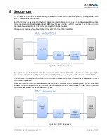
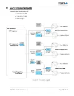
Each of the two Conversion Clocks (Conversion Clock 1 and Conversion Clock 2) may be selected as the
Sequencer Conversion Clock Source in the ADC Sequencer Control Register or the DAC Sequencer Control
Register to define the ADC Sequencer's conversion rate or the DAC Sequencer’s conversion rate.
The Frame Trigger (in combination with a Conversion Clock) is used for sequencers configured to operate in
Frame Mode. For example, the Frame Trigger can be used to synchronize/align ADC Frames and DAC
Frames. The Frame Trigger Generator output is generated (phase locked) to either the Conversion Clock 1
Generator output or to the Conversion Clock 2 Generator output.
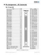
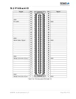
Each of these three Conversion Signals can either be generated on-board or can be generated by an
external device and input via Front I/O or P14 Back I/O.
If generated on-board, all three Conversion Signals may optionally be driven out on either Front I/O or Back
I/O.
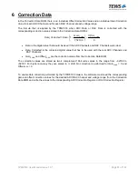
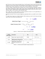
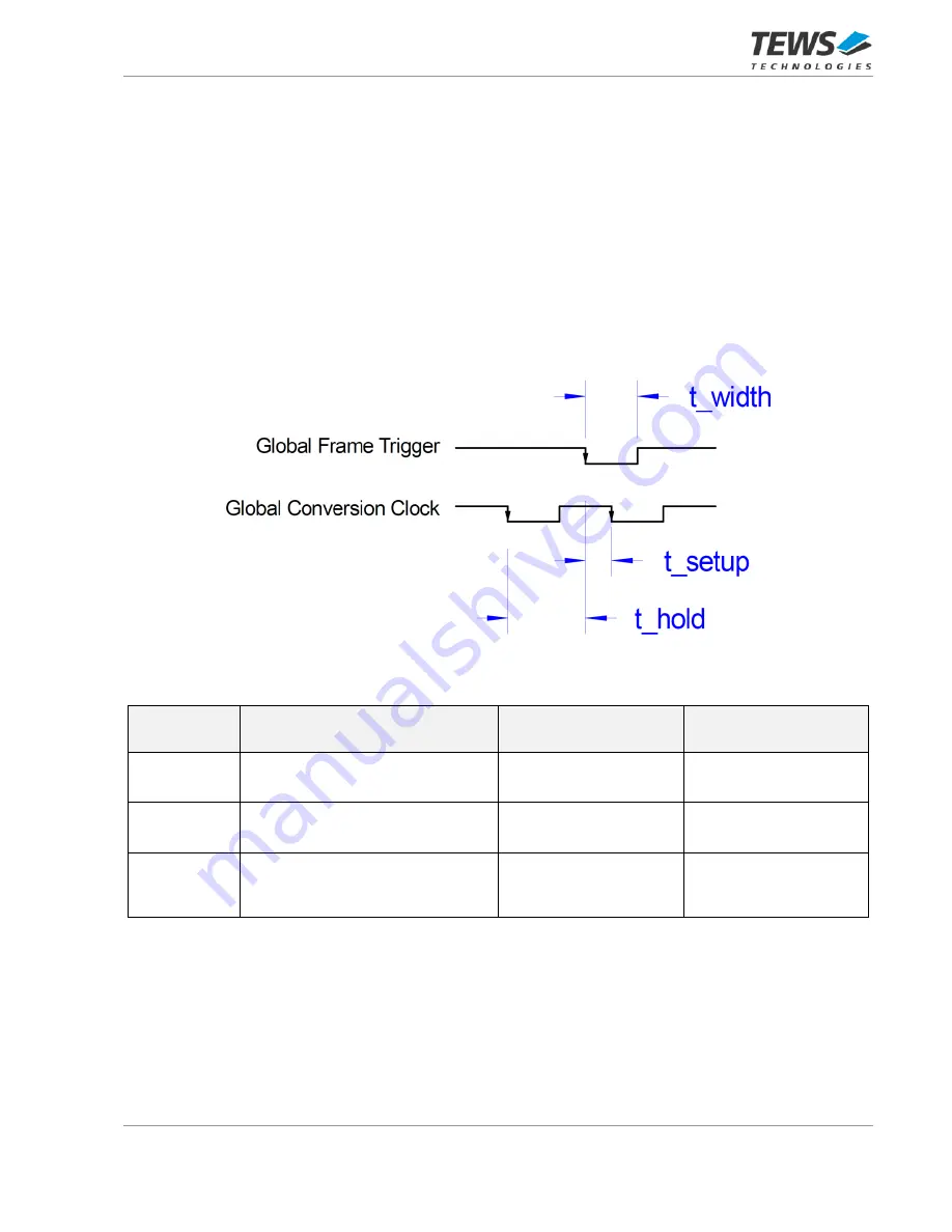
If a Global Frame Trigger and a Global Conversion Clock are input via Front I/O or P14 Back I/O these
signals need to meet certain timing requirements:
Figure 9-2 : Global Conversion Signals Timing Requirements
Timing
Requirement
Description
Min
Max
t_width
Global Frame Trigger Pulse Width
500ns
½ T
GLO_CON_CLK
t_hold
Global Conversion Clock Event to
next Global Frame Trigger Event
½ T
GLO_CON_CLK
- 250ns
-
t_setup
Global Frame Trigger Event to
next Global Conversion Clock
Event
250ns
-
Table 9-1 : Global Conversion Signals Timing Requirements


