TPMC533 User Manual Issue 1.0.1
Page 103 of 107
Multi-board Synchronization
9.1
Using the Frame Mode in the ADC Sequencer Control Register and in the DAC Sequencer Control Register
allows multi-board synchronization.
In a multi-board application, one PMC is operating as the multi-board master card while the other cards are
operating as multi-board target cards.
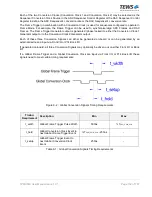
The Frame Trigger signal is generated by the Frame Trigger Generator on the master card. It is either
aligned to Conversion Clock 1 or to Conversion Clock 2. The Frame Trigger and the associated Conversion
Clock are distributed to all cards involved in the multi-board application either via Front I/O or via P14 Back
I/O (
Conversion Signals Generator Output Driver Register
).
The multi-board master’s Frame Trigger (Global Frame Trigger) and the multi-board master’s Conversion
Clock (Global Conversion Clock) must be connected to the Global Frame Trigger and Global Conversion
Clock Front I/O or P14 Back I/O pins of all target cards in the multi-board application.
All cards involved in the multi-board application
(including the master card)
must use the Front I/O or P14
Back I/O pin input signals as the signal source for both the Frame Trigger signal and the Conversion Clock
signal (
Conversion Signals Source Selection Register
).
All card's sequencers operating in Frame Mode are waiting for a Global Frame Trigger signal event to start
the sequencer conversion process.
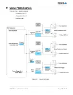
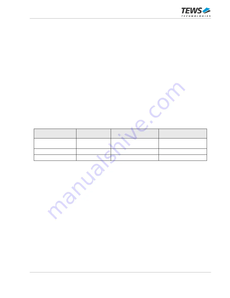
System Configuration
Conversion Signals
Generator Enable
Conversion Signals
Generator Output Driver
Conversion Signals Source
Selection
Single Card
Enabled
Output Driver disabled
Conversion Signal
Generators
Multi-board Master Card
Enabled
P14 Back I/O or Front I/O
P14 Back I/O or Front I/O
Multi-board Target Card
Disabled
Output Driver disabled
P14 Back I/O or Front I/O
Table 9-2 : Generator Enable, Generator Output Driver and Source Selection settings for different System
Configurations


