background image

www.ti.com

Software Installation

3.3

Update USB Driver

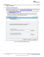
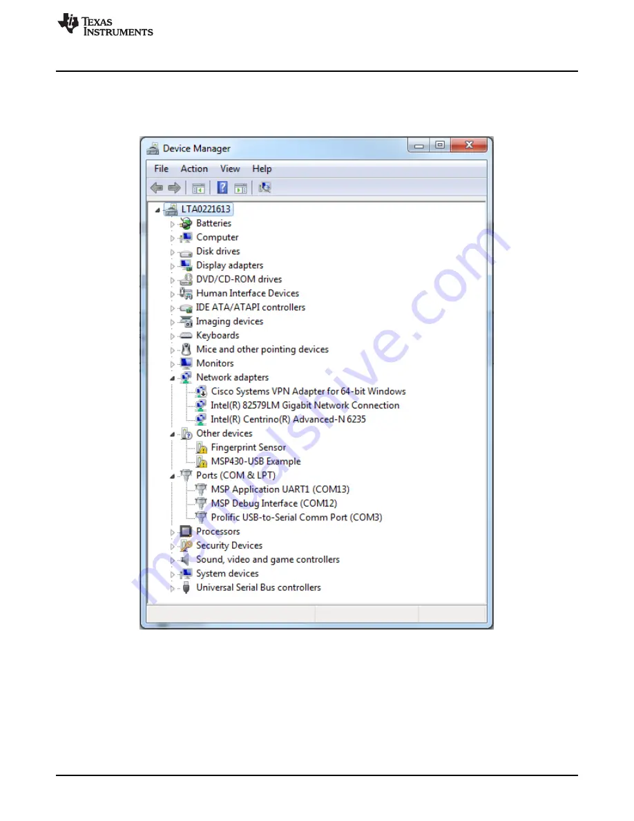
1. Before launching the ADC1x1S62x software, connect the ADC161S626EVM board to a USB port of

the PC. Go to Device Manager and find MSP43-USB Example. Right click and select Update Driver
Software.

Figure 10. Driver Not Installed

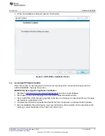
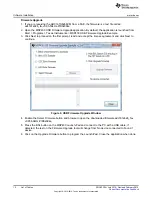
2. On the next screen, select the Browse my computer for driver software option, go to the directory of

the install files and select the MSP430_CDC_PID0x094e_ADC_DAC_EVMs.inf file.

3. If prompted with a warning window, select Install this Driver Anyway. Close the installation window

when done. The device manager should now display a TI_ADC_DAC_EVMs item followed by a COM
port number.

13

SNOU130A – July 2014 – Revised February 2015

List of Tables

Submit Documentation Feedback

Copyright © 2014–2015, Texas Instruments Incorporated

Summary of Contents for ADC161S626

Page 1: ...ADC161S626EVM User s Guide User s Guide Literature Number SNOU130A July 2014 Revised February 2015 ...

Page 2: ...6 Circuit 9 3 Software Installation 10 3 1 Graphical User Interface GUI 10 3 2 Launchpad Firmware Update 11 3 3 Update USB Driver 13 4 Board Setup and Operation 15 4 1 Board Setup 15 4 2 Launching the Software 16 5 Board Layout 19 6 Schematic 24 7 Bill of Materials 25 Revision History 26 2 Table of Contents SNOU130A July 2014 Revised February 2015 Submit Documentation Feedback Copyright 2014 2015 ...

Page 3: ...2 10 Driver Not Installed 13 11 Driver Authentication Warning 14 12 Example COM Port Number 14 13 ADC161S626EVM Hardware Connection 15 14 The Main Menu of ADC1x1S62x Software 16 15 Selectable Fields in GUI 17 16 Testing in the GUI 18 17 Top Assembly Layer 19 18 Top Layer Routing 20 19 Power Layer Routing 21 20 Ground Layer Routing 22 21 Bottom Layer Routing 23 22 ADC161S626EVM DUT Schematic 24 3 S...

Page 4: ...Tables 1 Device and Package Configurations 5 2 ADC161S626EVM Bill of Materials 25 4 List of Tables SNOU130A July 2014 Revised February 2015 Submit Documentation Feedback Copyright 2014 2015 Texas Instruments Incorporated ...

Page 5: ...ughout the A D converter to provide excellent common mode signal rejection The EVM contains an LMP8350 and an ADC161S626 The LMP8350 is an ultra low distortion fully differential amplifier designed for driving high performance precision analog to digital converters ADC The user can use the LMP8350 to drive the ADC or test the performance of ADC161S626 directly The evaluation board communicates wit...

Page 6: ... and connectors on the ADC161S626EVM The top view of this board is shown in Figure 1 The detailed introductions for each part are shown as follows Figure 1 ADC161S626 Evaluation Board 6 List of Tables SNOU130A July 2014 Revised February 2015 Submit Documentation Feedback Copyright 2014 2015 Texas Instruments Incorporated ...

Page 7: ...Voltage VREF The reference pin VREF should be supplied by external voltage through the test point VREF EXT while pin 1 and pin 2 in the JVREF header should be shorted Otherwise the VREF pin should be connected with the U3 LM4120AIM5 4 1 a 4 096 V precision micro power low dropout voltage reference when pin 2 and pin 3 in the JVREF header are shorted Figure 3 Reference Voltage VREF 7 SNOU130A July ...

Page 8: ...Driving Circuit about LM8350 2 4 The Interface between LM8350 and ADC161S626 The standard 100 mils header J2 is the interface between LM8350 and ADC161S626 Pin 1 and pin 5 are the differential output of LM8350 The OUT and OUT are test points to probe the LM8350 differential output Pin 2 and pin 4 are the differential input of ADC161S626 The user can select LM8350 to drive ADC just shorting pins 1 ...

Page 9: ...s of reference voltage VREF C13 and C14 are the bypass capacitors of the analog supply and digital input output supply respectively The ADC161S626 communicates with the launch pad through the 3 wire SPI interface SCLK DOUT and CS Figure 6 The ADC161S626 Circuit 9 SNOU130A July 2014 Revised February 2015 List of Tables Submit Documentation Feedback Copyright 2014 2015 Texas Instruments Incorporated...

Page 10: ... www ti com product adc161s626 scroll down to the Software section and download the latest evaluation software 2 Unzip the downloaded file into a known directory and run the setup exe file located in Unzip location ADC161S626EVM EVM_GUI ADC1x1S62x Installer Volume Follow the pop screen instructions by clicking the Next button to install the software Figure 7 ADC1x1S62x Installation Directory 10 Li...

Page 11: ...Software 2 Scroll down to the end of the page to find the USB Collateral Installers section 3 Click on MSP430_USB_Firmware_Upgrade_Example x x x Setup exe to download the tool the page will redirect to a submission form 4 Complete the information requested and submit the form if approved a download button appears 5 Run the installation file and follow the on screen instructions until completion Wh...

Page 12: ...eement and click Next to continue Figure 9 USB Firmware Upgrade Window 4 Enable the Select Firmware button and browse to open the downloaded firmware adc161s626_fw v0 95 50kHz PID0x094e 5 Press the BSL button on the MSP430 Launch Pad and connect to the PC with a USB cable if detected the text on the Firmware Upgrade tool will change from No device connected to Found 1 device 6 Click on the Upgrade...

Page 13: ...en select the Browse my computer for driver software option go to the directory of the install files and select the MSP430_CDC_PID0x094e_ADC_DAC_EVMs inf file 3 If prompted with a warning window select Install this Driver Anyway Close the installation window when done The device manager should now display a TI_ADC_DAC_EVMs item followed by a COM port number 13 SNOU130A July 2014 Revised February 2...

Page 14: ...www ti com Figure 11 Driver Authentication Warning Figure 12 Example COM Port Number 14 List of Tables SNOU130A July 2014 Revised February 2015 Submit Documentation Feedback Copyright 2014 2015 Texas Instruments Incorporated ...

Page 15: ...lt the ADC161S626EVM JVREF should be jumped for pin2 3 This allows the VREF of the ADC to be sourced from an on board 4 096 V regulator The user can also use an external VREF by shorting pin1 2 3 The outputs of the differential amplifier are connected with inputs of ADC161S626 by shorting pin1 2 and pin 4 5 on J2 by default Figure 13 ADC161S626EVM Hardware Connection 15 SNOU130A July 2014 Revised ...

Page 16: ...C1x1S62x Launching the software takes the user directly to the GUI as shown in Figure 14 There is a pull down menu in which the user can select ADC161S626 Figure 14 The Main Menu of ADC1x1S62x Software 16 List of Tables SNOU130A July 2014 Revised February 2015 Submit Documentation Feedback Copyright 2014 2015 Texas Instruments Incorporated ...

Page 17: ... only one usable channel In the output type tabs the user can choose mV or decimal to represent the output value There are two operation modes single mode and continuous mode Figure 15 Selectable Fields in GUI 17 SNOU130A July 2014 Revised February 2015 List of Tables Submit Documentation Feedback Copyright 2014 2015 Texas Instruments Incorporated ...

Page 18: ...tinuous mode the waveform chart displays the digital code output of the ADC161S626 Choose the burst mode and click Start Plot to catch and display the data Figure 16 Testing in the GUI 18 List of Tables SNOU130A July 2014 Revised February 2015 Submit Documentation Feedback Copyright 2014 2015 Texas Instruments Incorporated ...

Page 19: ...ut The following figures show the board layout for the ADC161S626EVM Figure 17 Top Assembly Layer 19 SNOU130A July 2014 Revised February 2015 List of Tables Submit Documentation Feedback Copyright 2014 2015 Texas Instruments Incorporated ...

Page 20: ...Board Layout www ti com Figure 18 Top Layer Routing 20 List of Tables SNOU130A July 2014 Revised February 2015 Submit Documentation Feedback Copyright 2014 2015 Texas Instruments Incorporated ...

Page 21: ...www ti com Board Layout Figure 19 Power Layer Routing 21 SNOU130A July 2014 Revised February 2015 List of Tables Submit Documentation Feedback Copyright 2014 2015 Texas Instruments Incorporated ...

Page 22: ...Board Layout www ti com Figure 20 Ground Layer Routing 22 List of Tables SNOU130A July 2014 Revised February 2015 Submit Documentation Feedback Copyright 2014 2015 Texas Instruments Incorporated ...

Page 23: ...www ti com Board Layout Figure 21 Bottom Layer Routing 23 SNOU130A July 2014 Revised February 2015 List of Tables Submit Documentation Feedback Copyright 2014 2015 Texas Instruments Incorporated ...

Page 24: ...2 JA 7 JB 7 JB 6 JB 7 GND VREF 1 IN 2 IN 3 GND 4 GND 5 CS 6 DOUT 7 SCLK 8 VIO 9 VA 10 U1 ADC161S626CIMM 5V GND 0 1µF C13 GND 0 1µF C14 3 3V GND 1 8 3 6 4 5 2 7 OUT OUT EN Vcm V V U2 LMP8350MA 5V 0 01µF C8 GND GND 2 IN 4 OUT 5 EN 3 REF 1 GND U3 LM4120AIM5 4 1 NOPB 5V GND 1µF C1 GND 0 047µF C2 GND Vref Vref GND 1 00k R5 1 00k R6 1 2 3 JVREF 0 1µF C5 10µF C6 GND GND GND 5V VEN VEN 180 R9 470pF C11 0 ...

Page 25: ...eptacle 10x2 100mil TH PPPC102LFBN RC Solutions Sullins Connector JVREF 1 Header 100mil 3x1 Tin plated TH PEC03SAAN Solutions R1 1 RES 0 ohm 5 0 1W 0603 CRCW06030000Z0EA Vishay Dale R5 R6 2 RES 1 00k ohm 1 0 1W 0603 CRCW06031K00FKEA Vishay Dale R7 R8 2 RES 1 00k ohm 1 0 125W 0805 CRCW08051K00FKEA Vishay Dale R9 R10 2 RES 180 ohm 1 0 1W 0603 RC0603FR 07180RL Yageo America SH J1 SH J2 SH J3 3 Shunt ...

Page 26: ...4 to A Revision Page Updated Figure 22 24 NOTE Page numbers for previous revisions may differ from page numbers in the current version 26 Revision History SNOU130A July 2014 Revised February 2015 Submit Documentation Feedback Copyright 2014 2015 Texas Instruments Incorporated ...

Page 27: ...esponsible for compliance with all legal regulatory and safety related requirements concerning its products and any use of TI components in its applications notwithstanding any applications related information or support that may be provided by TI Buyer represents and agrees that it has all the necessary expertise to create and implement safeguards which anticipate dangerous consequences of failur...

Reviews: