Basic Test Procedure
3.2
Test Set-up Connection
1. Connect the ADC32xx/ADC34xx EVM J13 connector to the TSW1400 EVM J3 connector
2. Connect 5 V to the TSW1400 J12 supply input connector and 5 V to the ADC32xx/34xx EVM J15
supply input connector
3. Provide a sample clock at the ADC32xx/34xx EVM J9 SMA connector
4. Provide a sine wave for the ADC32xx EVM J1 or J4 analog input and J1, J4, J5, or J8 of the ADC34xx
EVM
5. Connect a USB cable from the TSW1400 to the programming computer
6. For basic testing, the USB/SPI connection is not needed on the ADC32/34xx. Press SW1 to perform a
hardware reset. This will work with the default settings.
7. Verify the following jumper connections on the ADC32/34xx EVM:
•
JP1
– 2,3 default condition PDN is low
•
JP2, JP3, JP4, JP5
– Closed – default condition for SPI connection
•
JP6
– 1,2 default condition to select LDO power supply
•
JP7
– 1,2 default condition to select LDO power supply
3.3
ADC32/34xx and TSW1400 Setup Guide
Please reference the TSW1400 User’s Guide for more detailed explanations of the TSW1400 set-up and
operation. This document assumes the High-Speed Data Converter (HSDC) Pro software and the
TSW1400 hardware are installed and functioning properly.
The ADC32/34xx EVM requires High-Speed
Data Converter Pro software version 2.6 or higher with TSW1400 hardware of Rev D (or higher).
Single tone FFT test
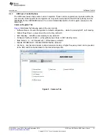
1. Start the HSDC Pro GUI program. When the program starts, select the ADC tab and then select
ADC324x_2W_14bit.ini or ADC344x_2W_14bit.ini device in the
Select ADC
drop down menu.
Figure 14. Select ADC32xx or 34xx in the HSDC Pro GUI Program
2. When prompted with
Load ADC Firmware?
, select
YES
3. Select Single Tone FFT Test under
Test Selection
4. Select number of sample points (and resulting number of FFT bins) to be used. The example shown in
has 65536 samples.
5. Enter the ADC32/34xx Sampling rate. The example shown in
has the sample rate set at 125
Msps (filtered clock input around 10 dBm).
6. Enter the input frequency desired. If the clock and input frequency signal generators are synchronized,
then make sure the checkbox for coherent frequency is checked and set the input frequency signal
generator to the input frequency displayed. The example shown in
has the input frequency
set at 10MHz (9.98878479MHx if coherent). Filtered signal input around 10 dBm – adjust to achieve –1
dBFs on the HSDC Pro FFT.
7. Select channel 1, 2, 3, or 4 depending on the channel to which the signal generator is connected
8. Press the
Capture
button on the HSDC Pro GUI
22
ADC3xxx, ADC3xJxx EVM User’s Guide
SLAU579A – June 2014 – Revised September 2014
Copyright © 2014, Texas Instruments Incorporated


