Basic Test Procedure
26
SLAU579D – June 2014 – Revised August 2018
Copyright © 2014–2018, Texas Instruments Incorporated
ADC3xxxEVM and ADC3xJxxEVM
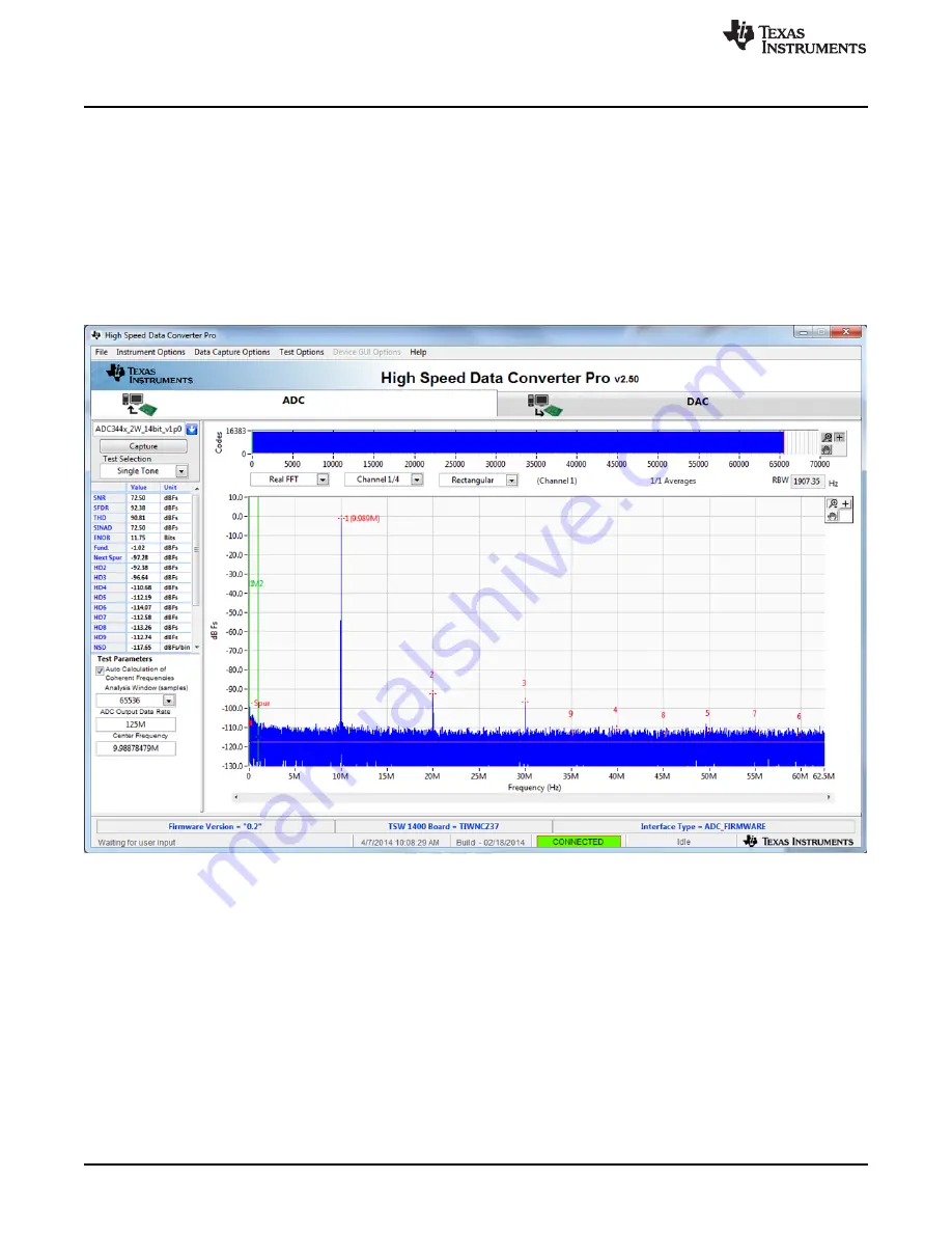
5. Enter the ADC32/34xx Sampling rate. The example shown in
has the sample rate set at 125
MSPS (filtered clock input around 10 dBm).
6. Enter the input frequency desired. If the clock and input frequency signal generators are synchronized,
then make sure the checkbox for coherent frequency is checked and set the input frequency signal
generator to the input frequency displayed. The example shown in
has the input frequency
set at 10MHz (9.98878479MHx if coherent). Filtered signal input around 10 dBm – adjust to achieve –1
dBFs on the HSDC Pro FFT.
7. Select channel 1, 2, 3, or 4 depending on the channel to which the signal generator is connected
8. Press the
Capture
button on the HSDC Pro GUI
9. Observe an FFT result similar to that of
Figure 17. ADC3xxx Operating in 14-Bit Mode at 125 MSPS With a 10-MHz Input Signal
If the basic capture at this point is correct, then the front panel options of the SPI GUI and the front panel
options of the TSW1400 GUI may be varied as desired to test out different device options.


