Introduction
3
SLAU579D – June 2014 – Revised August 2018
Copyright © 2014–2018, Texas Instruments Incorporated
ADC3xxxEVM and ADC3xJxxEVM
1
Introduction
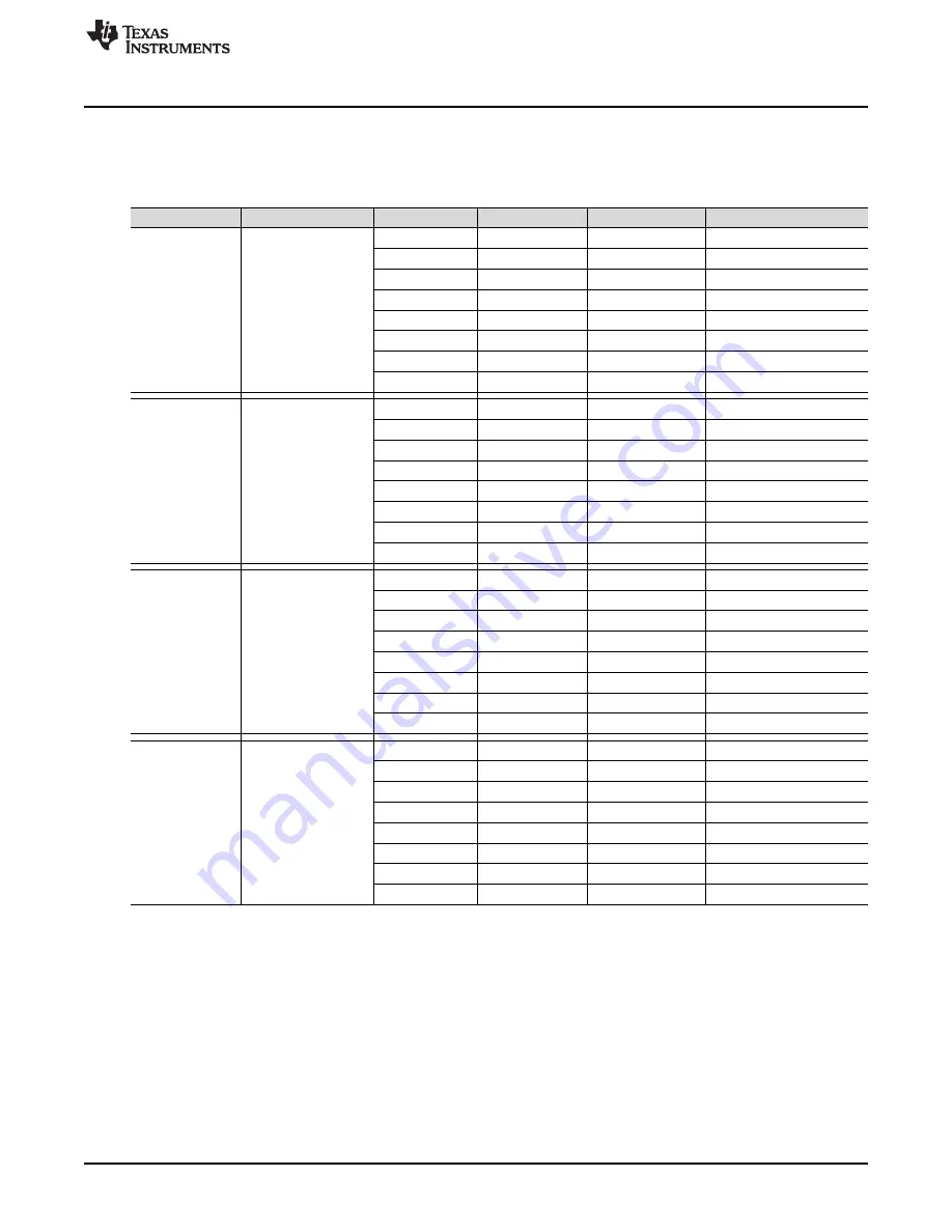
The family of parts and 32 associated EVMs are categorized in
Table 1. ADC3xxx Family of Devices and EVMs
Interface
Number of Channels
ADC Device
Number of Bits
Maximum MSPS
EVM
sLVDS
Dual
12
25
12
50
12
80
12
125
14
25
14
50
14
80
14
125
sLVDS
Quad
12
25
12
50
12
80
12
125
14
25
14
50
14
80
14
125
JESD204B
Dual
12
50
12
80
12
125
12
160
14
50
14
80
14
125
14
160
JESD204B
Quad
12
50
12
80
12
125
12
160
14
50
14
80
14
125
14
160
There are three package sizes and pinouts for all of these parts. The sLVDS dual devices use a 7-mm ×
7-mm, 48-pin QFN package. The sLVDS quad devices use an 8-mm × 8-mm, 56-pin QFN package. The
dual and quad JESD204B device share the same package using a 7-mm × 7-mm, 48-pin QFN package
The dual ADCs comprise two buffered inputs, two ADC cores, and a common input clock circuit. The quad
ADCs comprise four buffered inputs, four ADC cores, and a common input clock circuit. The sLVDS
versions have a 2-wire interface per ADC (two pairs of p/n signals)—for the dual, this means two sets of 2-
wire interfaces (four p/n pairs), the quad has four sets of 2-wire interfaces (eight p/n pairs). Each of these
2-wire interfaces can be operated in 1-wire mode (14x serialization), or 2-wire mode (7x serialization). For
the 12-bit devices, this equates to 12x and 6x serialization. The JESD204B versions have one lane per
ADC core. For the dual, this means there are two lanes per device, and four lanes per device for the
quad. See the respective device data sheet for more information on sLVDS serialization and JESD204B
lane configurations.


