CLK IN
14bit
ADC
14bit
ADC
14bit
ADC
14bit
ADC
Digital
Block
+
Output
Formatter
DCLK
DAB P/M sLVDS
2
DCD P/M sLVDS
2
Power
Supply
Circuits
USB
To
SPI
5V
USB
ADC34xx
CH A
CH B
CH C
CH D
FCLK
Introduction
4
SLAU579D – June 2014 – Revised August 2018
Copyright © 2014–2018, Texas Instruments Incorporated
ADC3xxxEVM and ADC3xJxxEVM
1.1
EVM Block Diagram
and
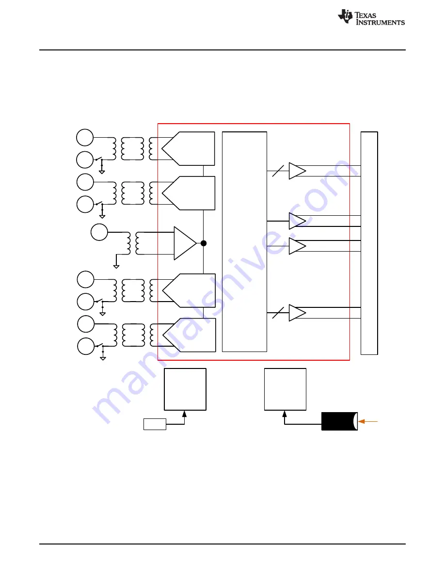
show simplified block diagrams of the default configuration of the EVM. The two or
four analog inputs are supplied to the EVM through a single-ended SMA connection, then transformer
coupled to turn the single-ended signal into a balanced differential signal, and then input to the ADC32xxx
or ADC34xxx. A dual transformer input circuit is used for better phase and amplitude balance of the input
signal than is typically produced by a single transformer input circuit.
Figure 1. Simplified ADC344x EVM Block Diagram


