Revision History
22
SLAU620A – April 2016 – Revised May 2016
Copyright © 2016, Texas Instruments Incorporated
Revision History
generated on the EVM, either by the LMX2582 or the LMK04828. The default configuration for the
EVM is for the LMX2582 to be the clock source to the ADC while in internal clock mode. Unsolder the
two AC coupling caps from positions C409 and C410 and solder them into positions C431 and C432.
This disconnects the ADC device clock from the LMX2582 outputs and instead connects the
LMK04828 device clock output to be the clock source to the ADC. There need not be any input to the
J5 external clock SMA. If the LMK04828 is to be synchronized to the timebase of the signal generator
used for the analog input, then connect the 10-MHz sync signal from the signal generator to the
LMK04828 reference input J7. The LMK04828 is still used to supply SYSREF to the ADC and
Clock/SYSREF to the TSW14J56.
2. The procedure for loading the configuration files is as previously described: the LMK04828 is
configured, followed by the ADC32RFxx. There are individual cfg files for many of the common
frequencies that the EVM may be asked to support, all generated from the 122.88-MHz VCXO installed
on the EVM. The configuration files used for the ADC32RF45 are slightly different than those for the
ADC32RF80, and they are not interchangeable. The clock rate from the EVM to the TSW14J56 is
different for the RF80 with DDC than it is for the RF45 5-sample mode, and the SYSREF frequencies
are different. Also, the LMK04828 is configured to pass a copy of the 122.88 VCXO reference on to the
LMX2582.
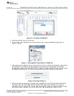
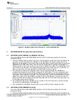
3. After configuring the LMK04828, reset the ADC by way of SW1 and then configure the ADC.
Revision History
NOTE: Page numbers for previous revisions may differ from page numbers in the current version.
Changes from Original (April 2016) to A Revision
..........................................................................................................
Page
•
Updated
EVM Feature Locations
image.
...............................................................................................
•
Deleted example test setup image.
.....................................................................................................
•
Updated
ADC32RFxxEVM GUI Bench Setup Block Diagram
image.
..............................................................
•
Updated
Example Capture from Channel A – 5 Sample Mode
image.
...........................................................
•
Updated
Example Capture From Channel A – 8x Decimation Mode
image.
....................................................

