background image

www.ti.com

ADS1115EVM-PDK Kit Operation

6.1

Installing the ADCPro Software

CAUTION

Do not connect the ADS1115EVM-PDK before installing the software on a
suitable PC. Failure to observe this caution may cause Microsoft Windows to
not recognize the ADS1115EVM-PDK as a connected device.

The latest software is available from the TI website at

http://www.ti.com

. Refer to the

ADCPro User Guide

for instructions on installing and using ADCPro.

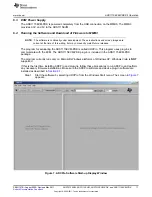
To install the ADS1115EVM-PDK plug-in, run the file: ads1115evm-pdk-plug-in-1.0.0.exe (1.0.0 is the
version number, and increments with software version releases). Double-click the file to run it; then follow
the instructions shown. You can also use the ADCPro Update Check feature to check for newer versions
of the ADS1115EVM-PDK plug-in, once you have installed a version of it.

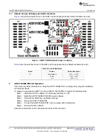
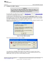
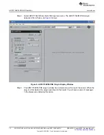
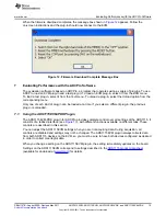
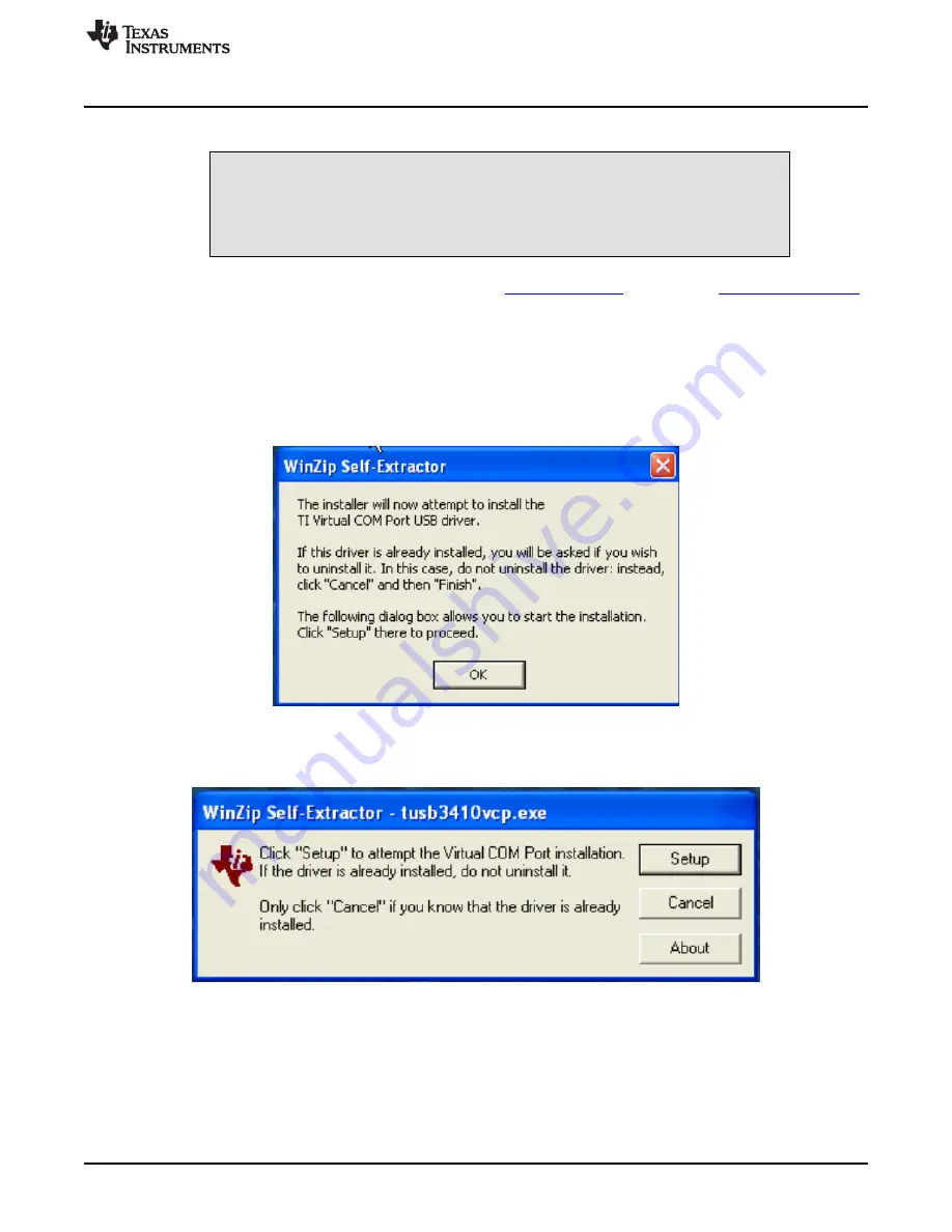
Follow the on-screen prompts. Once the ADCPro plug-in installs, you will be prompted to install the Virtual
COM port driver as shown in

Figure 2

.

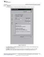
Figure 2. Virtual COM Port Installer

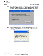
Press OK, and the screen shown in

Figure 3

displays.

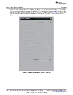
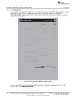
Figure 3. Virtual COM Port Setup

If you already have a TUSB3410 Virtual COM port driver installed on your system, select Cancel;
otherwise, press Setup and follow the on-screen prompts. You may be notified that the driver is not
digitally signed. If this occurs, select Continue Anyway and proceed.

7

SBAU157B

August 2009

Revised May 2011

ADS1015EVM, ADS1115EVM, ADS1015EVM-PDK, and ADS1115EVM-PDK

Submit Documentation Feedback

Copyright

©

2009

2011, Texas Instruments Incorporated

Summary of Contents for ADS1015EVM

Page 1: ...1015 or ADS1115 device Complete circuit descriptions schematic diagrams and bills of material are included in this document The following related documents are available through the Texas Instruments web site at http www ti com EVM Compatible Device Data Sheets Device Literature Number ADS1015 SBAS473 ADS1115 SBAS444 SN74LVC2G125 SCES204M PCA9306 SCPS113I ADCPro is a trademark of Texas Instruments...

Page 2: ...dow 11 8 ADS1115EVM PDK Plug In Display Window 12 9 Connection Timeout 13 10 Firmware Download Message Box 13 11 Firmware Download Progress Indicator 14 12 Firmware Download Complete Message Box 15 13 Device 1 Tab 17 14 About Tab 19 15 Progress Bar While Collecting Data 20 List of Tables 1 J1 Analog Interface Pinout 4 2 J3 Serial Interface Pins 4 3 J2 Configuration Power Supply Input 5 4 JMP1 Conf...

Page 3: ...ion Software User s Guide literature number SBAU128 available for download from the TI web site This manual covers the operation of both the ADS1015 ADS1115EVM and the ADS1015EVM PDK ADS1115EVM PDK Throughout this document the abbreviation EVM and the term evaluation module are synonymous with the ADS1015 ADS1115EVM For clarity of reading the rest of this manual will refer only to the ADS1115EVM o...

Page 4: ...his header socket provides access to the digital control and serial data pins of the ADC Consult Samtec at http www samtec com or call 1 800 SAMTEC 9 for a variety of mating connector options All logic levels on J3 are 3 3V CMOS except for the I2 C pins These pins conform to 3 3V I2 C rules Table 2 describes the J3 serial interface pins Table 2 J3 Serial Interface Pins Pin No Pin Name Signal Name ...

Page 5: ...t for the other digital devices Must be connected for operation 7 8 GND Connects DGND to AGND Switch S1 selects the supply voltage used to feed JMP1 and the respective VDDs shown in Table 4 S1 may be switched to VA 5VD or 3 3VD from power connector J2 5 EVM Operation This section provides information on the analog input digital control and general operating conditions of the ADS1115EVM 5 1 Analog ...

Page 6: ...sing the ADS1115EVM PDK including setup program installation and program usage To prepare to evaluate the ADS1115 with the ADS1115EVM PDK complete the following steps Step 1 Install the ADCPro software if not already installed on a PC Step 2 Install the ADS1115EVM PDK EVM plug in software Step 3 Complete the USB driver installation process Step 4 Set up the ADS1115EVM PDK Step 5 Connect the ADS111...

Page 7: ...s shown You can also use the ADCPro Update Check feature to check for newer versions of the ADS1115EVM PDK plug in once you have installed a version of it Follow the on screen prompts Once the ADCPro plug in installs you will be prompted to install the Virtual COM port driver as shown in Figure 2 Figure 2 Virtual COM Port Installer Press OK and the screen shown in Figure 3 displays Figure 3 Virtua...

Page 8: ...e ADS1115EVM PDK Step 1 Unpack the ADS1115EVM PDK kit Step 2 Set the switches on the MMB3 as described below as Figure 4 illustrates Set switch SW4 to the right Set the DAC switch SW5 to the OUT position to the right Figure 4 MMB3 Switch Locations 8 ADS1015EVM ADS1115EVM ADS1015EVM PDK and ADS1115EVM PDK SBAU157B August 2009 Revised May 2011 Submit Documentation Feedback Copyright 2009 2011 Texas ...

Page 9: ...15EVM to MMB3 Step 4 Set the jumpers and switches on the ADS1115EVM as shown in Figure 1 note that these settings are the factory configured settings for the EVM 9 SBAU157B August 2009 Revised May 2011 ADS1015EVM ADS1115EVM ADS1015EVM PDK and ADS1115EVM PDK Submit Documentation Feedback Copyright 2009 2011 Texas Instruments Incorporated ...

Page 10: ...and has a joystick for control of functions on the board when it is not controlled by a PC These features are experimental and not supported in the ADS1115EVM PDK at this time The MMB3 derives power from the USB interface and generates 5VD 3 3V and 1 8V as well as 5VA and 5VA and 10V The 10V is supplied to the daughtercard power connector as VA and VA CAUTION When using the ADS1115EVM connected to...

Page 11: ...15EVM PDK plug in is included in the ADS1115EVM PDK package The program currently runs only on Microsoft Windows platforms of Windows XP Windows Vista is NOT supported If this is the first time installing ADCPro and plug ins follow these procedures to run ADCPro and perform any necessary firmware installations Make sure the ADCPro software and device plug in software are installed as described in ...

Page 12: ...indow Step 3 The ADS1115EVM PDK plug in window has a status area at the top of the screen When the plug in is first loaded the plug in searches for the board You will see a series of messages in the status area indicating this action 12 ADS1015EVM ADS1115EVM ADS1015EVM PDK and ADS1115EVM PDK SBAU157B August 2009 Revised May 2011 Submit Documentation Feedback Copyright 2009 2011 Texas Instruments I...

Page 13: ...used Figure 9 Connection Timeout Step 5 The plug in will detect whether or not the board has the correct firmware loaded The first time you use the ADS1115EVM PDK the firmware for the MMB3 may need to be downloaded to the MMB3 If the firmware needs to be loaded you will see a screen as shown in Figure 10 Figure 10 Firmware Download Message Box 13 SBAU157B August 2009 Revised May 2011 ADS1015EVM AD...

Page 14: ... so the progress is updated in the message at the top of the ADS1115 plug in window as Figure 11 shows The firmware is saved in flash memory on the MMB3 so this operation should only need to be performed once Figure 11 Firmware Download Progress Indicator 14 ADS1015EVM ADS1115EVM ADS1015EVM PDK and ADS1115EVM PDK SBAU157B August 2009 Revised May 2011 Submit Documentation Feedback Copyright 2009 20...

Page 15: ...Plug in The ADS1115EVM PDK plug in for ADCPro provides complete control over all settings of the ADS1115 It consists of a tabbed interface see Figure 13 with different functions available on different tabs These controls are described in this section You can adjust the ADS1115EVM settings when you are not acquiring data During acquisition all controls are disabled and settings may not be changed T...

Page 16: ...he data The ADS1015EVM PDK allows the Data Rate control to set the data rate to 128 256 500 920 1600 2500 or 3300 SPS The MMB3 does not have the capability to send every sample at data rates above 920 SPS when a data rate higher than this is selected the data points collected will not be continuous The ADS1015 will operate at the higher data rate but data will be collected at 920 SPS skipping some...

Page 17: ...13 is the primary tab that controls all features of the ADS1115 Device 1 refers to U1 on the ADS1115EVM Figure 13 Device 1 Tab 17 SBAU157B August 2009 Revised May 2011 ADS1015EVM ADS1115EVM ADS1015EVM PDK and ADS1115EVM PDK Submit Documentation Feedback Copyright 2009 2011 Texas Instruments Incorporated ...

Page 18: ...hat a valid address has been found on the bus The Mux Setting control determines which set of inputs is used displayed as AINP AINN where AINP is the input connected to the positive input of the ADC and AINN is the input connected to the negative input of the ADC Selections available are AIN0 AIN1 AIN0 AIN3 AIN1 AIN3 AIN2 AIN3 AIN0 GND AIN1 GND AIN2 GND or AIN3 GND The PGA Gain control sets the PG...

Page 19: ...show the version numbers of the plug in and firmware code respectively The Notes indicator will show manufacturing information about the EVM that is stored in the EVM EEPROM and may show relevant notes about the plug in or firmware code if there are any 19 SBAU157B August 2009 Revised May 2011 ADS1015EVM ADS1115EVM ADS1015EVM PDK and ADS1115EVM PDK Submit Documentation Feedback Copyright 2009 2011...

Page 20: ...115EVM PDK plug in disables all the front panel controls while acquiring and displays a progress bar as shown in Figure 15 Figure 15 Progress Bar While Collecting Data For more information on testing analog to digital converters in general and using ADCPro and Test plug ins refer to the ADCPro User Guide 20 ADS1015EVM ADS1115EVM ADS1015EVM PDK and ADS1115EVM PDK SBAU157B August 2009 Revised May 20...

Page 21: ...t used To do this a Select the COM port item and right click to access the Properties menu b In the properties select the Port Settings tab c Select the Advanced button d Select the desired COM port setting from the COM Port Number control This control will note if the COM port is in use or open 3 Press the USB RESET button on the MMB3 to reconnect If ADCPro stops responding while the ADS1115EVM P...

Page 22: ... pin 9 3 JMP1 JMP2 Header Strip 8 pin Samtec TSW 104 07 L D JMP3 10 2 JMP4 JMP5 Header Strip 2 pin Samtec TSW 102 07 L S 11 1 Q1 N Channel Enhancement Fairchild NDC7002N MOSFET 12 2 470 R3 R4 1 10 W Chip Resistor 5 Panasonic ERJ 3GEYJ471V 0603 13 6 1kΩ R1 R2 R5 R6 1 10 W Chip Resistor Panasonic ERJ 3GEYJ102V R8 R9 5 0603 14 1 200kΩ R7 1 10 W Chip Resistor Panasonic ERJ 3GEYJ204V 5 0603 15 0 RA1 Re...

Page 23: ...AGND 13 VCOM 15 AGND 17 AGND 19 J1 DAUGHTER ANALOG VA 2 5VA 4 AGND 6 VD1 8 5VD 10 VA 1 5VA 3 DGND 5 1 8VD 7 3 3VD 9 J2 DAUGHTER POWER GPIO0 2 DGND 4 GPIO1 6 GPIO2 8 DGND 10 GPIO3 12 GPIO4 14 SCL 16 DGND 18 SDA 20 CNTL 1 CLKX 3 CLKR 5 FSX 7 FSR 9 DX 11 DR 13 INT 15 TOUT 17 GPIO5 19 J3 DAUGHTER SERIAL C1 0 1uF C2 0 1uF VDD1 VDD2 VDD1 VDD2 R1 1K R2 1K VDD 1 2 3 4 5 6 7 8 JMP1 JPR 2X4 VDD1 VDD2 VDD VD...

Page 24: ...product This notice contains important safety information about temperatures and voltages For additional information on TI s environmental and or safety programs please contact the TI application engineer or visit www ti com esh No license is granted under any patent right or other intellectual property right of TI covering or relating to any machine process or combination in which such TI product...

Page 25: ...horized for use in safety critical applications such as life support where a failure of the TI product would reasonably be expected to cause severe personal injury or death unless officers of the parties have executed an agreement specifically governing such use Buyers represent that they have all necessary expertise in the safety and regulatory ramifications of their applications and acknowledge ...

Reviews: