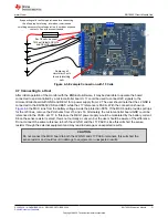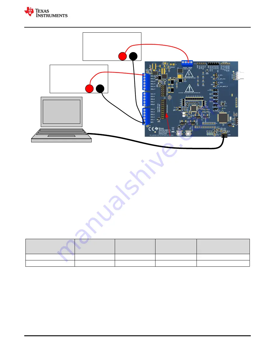
DC Power Supply
+ -
Install cell
simulator shunts
DC Power Supply
+ -
(Simulated load)
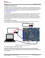
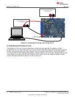
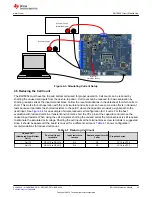
Figure 4-3. Simulating Current Setup
4.5 Reducing the Cell Count
The BQ76952 must have the top and bottom cells used for proper operation. Cell count can be reduced by
shorting the unused cell inputs from the next-to-top down. Cell count can be reduced for basic evaluation by
shorting unused cells at the input terminal block. Follow the recommendations in the datasheet for which cells to
short. This works for both operation with the cell simulator and cells, but can have some side effects in transient
tests because it parallels the shorted resistors to the cell IC where the capacitor provides a signal path to the
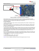
used input. See
for an example of simple reduced cell configuration for 14 cells. For the best
evaluation with reduced cells in a transient environment, short the VCx pins at the capacitor and remove the
unused input resistor. When using the cell simulator, shorting the unused cell at the terminal block is still required
to eliminate the simulated cell voltage. Shorting the cell inputs at the terminal block screw terminals is suggested
since it should be apparent if the board is re-used for a different cell count.
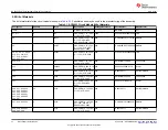
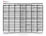
shows configuration
recommendations for reduced cell count.
Table 4-1. Reducing Cell Count
Unused Cell
(Numbered from Bottom
Cell 1)
Short cell input
terminals
Input resistor to
remove
Replace capacitor with
0 ohm
IC inputs shorted
Cell 15
CELL15 to CELL14
R3
C5
VC15 to VC14
Cell 14
CELL14 to CELL13
R4
C6
VC14 to VC13
BQ76952 Circuit Module Use
SLUUC33A – NOVEMBER 2019 – REVISED OCTOBER 2020
BQ76952 Evaluation Module
19
Copyright © 2020 Texas Instruments Incorporated


