Hardware Overview
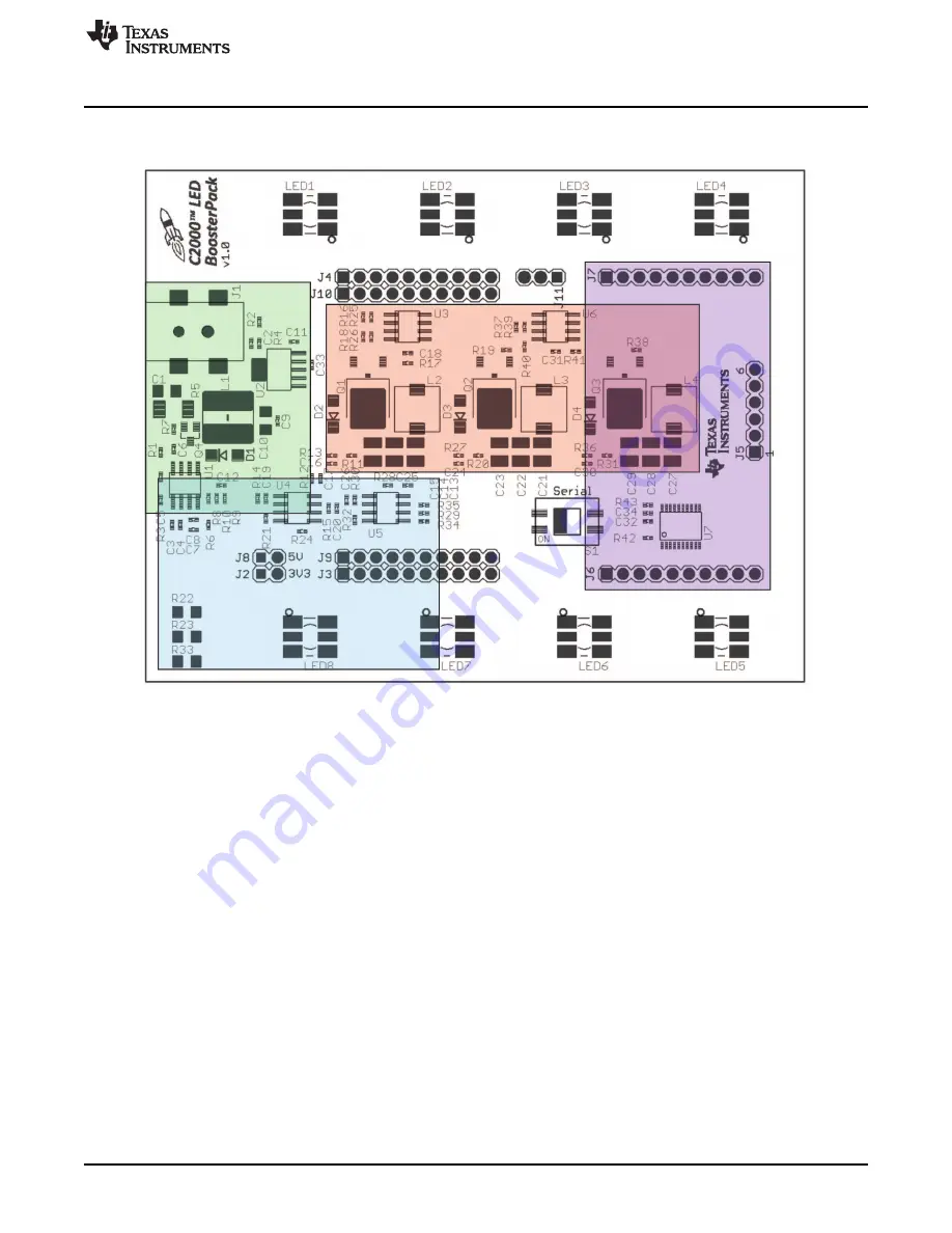
illustrates the position of these subsystems on the board. The use of a subsystem approach, for
different power stages, enables easy debug and testing of one stage at a time.
Figure 4. LED BoosterPack Subsytem Locations
3.2
Powering the Board
The LED BoosterPack has three separate power domains and two major modes of operation: two power
domains are the primary power rails that feeds the three DC/DC power stages and the auxiliary power
supply rails that power all of the support chips, and is used to power the LaunchPad. The question of
which mode of operation should be used depends on whether the board is being used for evaluation or for
experimentation.
•
Non-Isolated – Used to quickly show how the boards function with the supplied firmware. Power for the
LaunchPad is supplied via the USB. Power for the LED BoosterPack is supplied via the included 12 V
AC/DC adapter. With this configuration, your PC’s USB port is connected to the same ground as both
the LaunchPad and LED BoosterPack.
–
Jumpers JP1, JP2, and JP3 on the LaunchPad should have jumpers placed on each post.
–
Jumpers J2 and J8 on the LED BoosterPack should NOT have jumpers placed on each post.
–
Connect the USB to the LaunchPad.
–
Connect the included power adapter to the LED BoosterPacks’ J1.
7
SPRUHH9 – July 2012
C2000 LED BoosterPack
Copyright © 2012, Texas Instruments Incorporated


