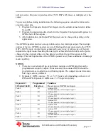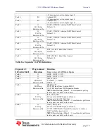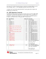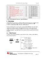
3.4
The C
resist
The C
outpu
The C
The C
3.5
The C
that i
conne
3.6
The C
and S
the m
Bootl
multi
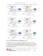
Figur
3.7
The I
comp
/INT1, /IN
C5535 DSP’
tor.
C5535 DSP’
uts. The outp
C5535 DSP’
C5535 DSP’
USB Con
C5535 DSP
s compliant
ector, P1, ha
MMC/SD
C5535 DSP
SD1. Interfac
micro SD car
loader. Inter
iplexed pins
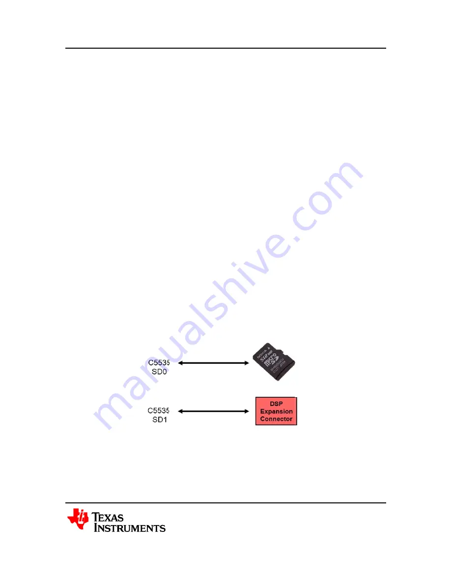
re 5. Micro
I2C
I2C peripher
pliant with th
C553
NT0, XF,
s /INT0 inpu
s /INT1 inpu
puts of the 2
s XF output
s Wakeup p
ntroller
USB contro
with the Un
as a micro-U
Dx Contro
has two emb
ce SD0 is co
rd is the defa
rface SD1 is
MMC1/I2S
SD Card P
ral provides
he Philips Se
35 DSPShield H/
In Collabo
WAKEUP
ut is routed t
ut is connect
Expanders a
t controls the
in can be mo
ller allows th
niversal Seria
USB form fac
oller
bedded Mult
onnected to a
ault boot sou
routed to th
1/GPIO[11:6
eripheral
an interface
emiconducto
/W Reference M
oration with S
P
to the DSP E
ted to the I2
are open-dra
e LED, D2. A
onitored on
he DSP to cr
al Bus Speci
ctor.
timedia Card
a micro SD c
urce for the C
e DSP Expa
6].
between the
ors I2C-bus s
Manual
Stanford Un
Expansion C
C to GPIO E
ain and are w
A logic “1” t
Test Point T
reate a high-
ification vers
d/Secure Dig
card adapter,
C5535 DSP’
ansion Conne
e DSP and ot
specification
niversity
Connector. It
Expander IC
wire-ORed to
turns on the
TP2.
-speed USB
sion 2.0. The
gital Control
, P2. For the
s on-chip RO
ector as part
ther devices
n (version 2.
Version 0.1
page
10
has a pull u
Cs’ /INT
ogether.
LED.
slave device
e DSP-USB
llers, SD0
e DSPShield
OM
t of the
s that are
1). The
1
up
e
,


