C5535 DSPShield H/W Reference Manual
Version 0.1
In Collaboration with Stanford University
page
29
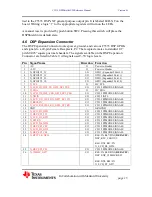
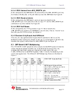
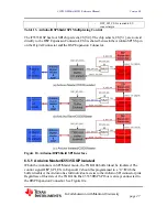
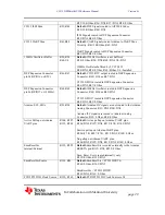
R25=10K Ohm, R26=DNI, R27=DNI, R28=0 Ohm
C5535 I2S2 Mux
R39, R40
Default:
I2S2 Signals routed to AIC3204 Codec
R39=10K Ohm, R40=DNI
I2S2 Signals routed to DSP Expansion Connector
R39=DNI, R40=0 Ohm
C5535 UART Mux
R41,R42
Default:
UART Signals routed Arduino to UART Mux
Circuitry. R41=10K Ohm, R42=DNI
UART Signals routed to DSP Expansion Connector
R41=DNI, R42=0 Ohm
12MHz Oscillator Buffer
R50, R54,
R60, U6
Default:
12MHz Oscillator is not buffered
R50=0 Ohm, R54=DNI, R60=DNI, U6=DNI
12MHz Oscillator buffered by LVC1G125
R50=DNI, R54=0 Ohm, R60=0Ohm, U6=Installed
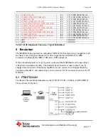
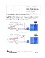
DSP Expansion Connector
pin24 (GPIO16 or RTC)
R66, R67
Default:
C5535 RTC output routed to DSP Expansion
Connecter. R66=0 Ohm, R67=DNI
C5535 GPIO16 routed to DSP Expansion Connector
R66=DNI, R67=0 Ohm
DSP Expansion Connector
pin26 (GPIO17 or 12MHz)
R68, R69
Default:
12MHz Oscillator routed to DSP Expansion
Connecter. R68=0 Ohm, R69=DNI
C5535 GPIO17 routed to DSP Expansion Connector
R68=DNI, R69=0 Ohm
Arduino SCL, SDA
R93, R94
Default:
Arduino I2C signals are not routed to the Arduino
Analog Connector. R93=DNI, R94=DNI
Arduino I2C signals are routed to Arduino Analog
Connector. R93=0 Ohm, R94=0 Ohm
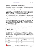
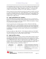
Active Pull up on Arduino
UART pins
R106, R107,
R112, R169
Default:
Active pullup on Arduino UART pins.
R106=DNI, R107=DNI, R112=4.7K, R169=DNI
Passive pullup on Arduino UART pins.
R106=4.7K, R107=4.7K, R112=DNI, R169=0 Ohm
No pullup on Arduino UART pins.
R106=DNI, R107=DNI, R112=DNI, R169=0 Ohm
EmuResetSrc
Internal/External
R119, R122
Default:
EmuResetSrc is routed externally to the Arduino
RESETN pin. R119=DNI, R122=0 Ohm
Emu_Reset_Src is routed internally only
R119=0 Ohm, R122=DNI
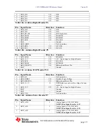
EmuResetSrc Source
R161, R63
Default:
EmuResetSrc = FT2232H RTS.
R161=0 Ohm, R163=DNI
EmuResetSrc = FT2232H DTR.
R161=DNI, R163=0 Ohm
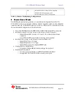
FTDI FT2232H Clock Source R150, R165,
Default:
FTDI FT2232H Clock Source is G1.

